New in SG-Lib 2.1
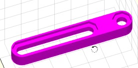
exp_2015_02_25- EXPERMENT to create 4x4 flexible hinge strips |
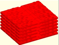 |
% exp_2015_02_25 - EXPERMENT to create 4x4 flexible hinge strips % (by Tim Lueth, VLFL-Lib, 2015-FEB-25 as class: EXPERIMENTS) % % Testing the possibility to create foil hinges by considering Erhard % (2008), page 361ff. The result is written into a binary STL file for % printing. % % LITERATURE: % - Erhard, Gunter (2008): Konstruieren mit Kunststoffen, Carl Hanser % Verlag, München, 4. Auflage % % SG=exp_2015_02_25 % === OUTPUT RESULTS ====== % SG: Solid geometry of the parts % |
exp_2015_02_24(s,w,e,x,y)- EXAMPLE how to create contour for a flexible Hinge |
 |
% exp_2015_02_24(s,w,e,x,y) - EXAMPLE how to create contour for a % flexible Hinge % (by Tim Lueth, VLFL-Lib, 2015-FEB-24 as class: KINEMATICS AND FRAMES) % % LITERATURE: % - Erhard, Gunter (2008): Konstruieren mit Kunststoffen, Carl Hanser % Verlag, München, 4. Auflage % % [PL,SG]=exp_2015_02_24([s,w,e,x,y]) % === INPUT PARAMETERS === % s: thickness of the hinge % w: radius to bend % e: strain value; default is 40% (0.4) % x: % y: % === OUTPUT RESULTS ====== % PL: Point List % SG: Solid Geoemtry % |
exp_2015_02_23 (r,th,st)- EXPERIMENT Testing perforated PLates by Air pressure and water pressure |
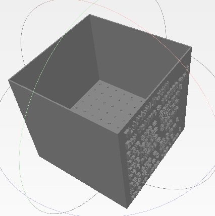 |
% exp_2015_02_23 (r,th,st) - EXPERIMENT Testing perforated PLates by Air % pressure and water pressure % (by Tim Lueth, VLFL-Lib, 2015-FEB-23 as class: MODELING PROCEDURES) % % This box can be filled with water (0.1l) or put ontop of the mouth to % breath trough. During the printing test performed 2015-02-24, it became % clear that it is possible to breath event trough hole with diameter % 0.25mm. (Status of: 2015-02-23) % % exp_2015_02_23([r,th,st]) % === INPUT PARAMETERS === % r: radius of the holes % th: height of the membrane plate % st: step size between the holes % |
exp_2015_02_22- EXPERIMENT that return rotating shells |
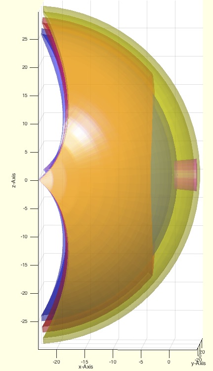 |
% exp_2015_02_22 - EXPERIMENT that return rotating shells % (by Tim Lueth, VLFL-Lib, 2015-FEB-22 as class: MODELING PROCEDURES) % % exp_2015_02_22 % |
SGofCPLsphere(CPL,Ri,d,ns)- returns solid geometry of a wrapped shell |
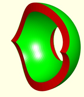 |
% SGofCPLsphere(CPL,Ri,d,ns) - returns solid geometry of a wrapped shell % (by Tim Lueth, VLFL-Lib, 2015-FEB-22 as class: MODELING PROCEDURES) % % See also: SGofCPLsphere, SGbeating, SGofCPLz, SGofCPLT % % SG=SGofCPLsphere(CPL,Ri,d,[ns]) % === INPUT PARAMETERS === % CPL: Closed Polygon List % Ri: Radius of the sphere used for wrapping % d: Thickness/height of the shell % ns: distance between auxiliary points; default is sofrd(Ri) % === OUTPUT RESULTS ====== % SG: Solid geometry % % EXAMPLE: Create an wrapped circular patch % SGofCPLshere(CPLofPL({PLcircle(30),PLcircle(10)}),20,0.5) % |
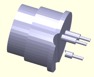
SGplateunder(SG,h,d)- returns a plate that is completely under the solid |
 |
% SGplateunder(SG,h,d) - returns a plate that is completely under the % solid % (by Tim Lueth, VLFL-Lib, 2015-FEB-22 as class: MODELING PROCEDURES) % % plate shape is a parallel projection of the outer contour onto the x/y % plane. This procedure is used by VLFLimageoftext. (Status of: % 2015-02-22) % % SGP=SGplateunder(SG,[h,d]) % === INPUT PARAMETERS === % SG: Solid Geometry % h: height of the plate; default is 1 % d: gap between solid and plate (can be negative) % === OUTPUT RESULTS ====== % SGP: Plate under SG % |
exp_2015_02_21 (R,stext,H,n)- creates a honory medallie |
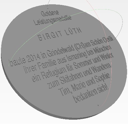 |
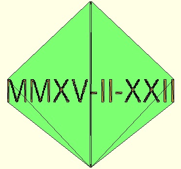
% exp_2015_02_21 (R,stext,H,n) - creates a honory medallie % (by Tim Lueth, VLFL-Lib, 2015-FEB-21 as class: MODELING PROCEDURES) % % exp_2015_02_21([R,stext,H,n]) % === INPUT PARAMETERS === % R: Radius; default is 35 % stext: Text; dafault is todays date % H: Height; default is R/10 % n: number of edges; default is circle % |
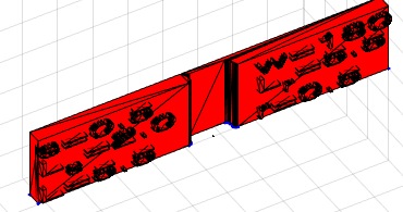
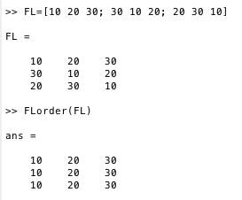
fourBarLinkageKit(task,2,3)- Creation kit for Four-Bar-Linkages |
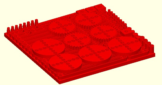 |
% fourBarLinkageKit(task,2,3) - Creation kit for Four-Bar-Linkages % (by Tim Lueth, VLFL-Lib, 2015-FEB-20 as class: KINEMATICS AND FRAMES) % % Depending on the input parameter this procedures returns parts of a % creation kit or a complete creation kit for physical experiments with % 4-Bar-linkages, gears etc: % It is similar to exp_2015_02_19 but with a more primitive modeler. % 'Knob': Knob for turning parts manually or as stopper % 'Bar': Basic elements of a linkage % 'Spacer': spacing element required for some configurations % 'Bolt': turning bolt as axis to connect two bars as joint % 'Shaft': shaft for fixed connection between two bars/parts % 'Wheel': Turning wheel with sockets for shafts and bolts % 'Gear': Turning gear (m=1) with sockets for shafts and bolts % 'Brick': Basic element with sockets for shafts and bolts % 'Plate': Square grid of bricks as base plate for experiments % 'Test': Small plate plus limited numbers of bars for test the 3D-Printer % 'all': All parts for a 4-Bar-Linkage construction kit % 'kit': Same as all but including a box/case % % (Status of: 2015-02-20) % % SG=fourBarLinkageKit([task,2,3]) % === INPUT PARAMETERS === % task: String for Task, default is bar % 2: 2nd parameter for shapes % 3: 3rn parameter for shapes/mode % === OUTPUT RESULTS ====== % SG: % % EXAMPLE: % fourBarLinkageKit ('gear') % fourBarLinkageKit ('all') % fourBarLinkageKit ('kit') % % |
SGstretching(A,dx,xlim)- cuts a solid geometry in x and stretches in x |
 |
% SGstretching(A,dx,xlim) - cuts a solid geometry in x and stretches in x % (by Tim Lueth, VLFL-Lib, 2015-FEB-20 as class: SURFACES) % % A=SGstretching(A,dx,xlim) % === INPUT PARAMETERS === % A: Solid geometry % dx: add d to all x-coodinates % xlim: for all x-coordinates > xlim % === OUTPUT RESULTS ====== % A: Stretched solid geoemtry % |
SGstripfields(SG)- remove unneccessary fields in SG structs |
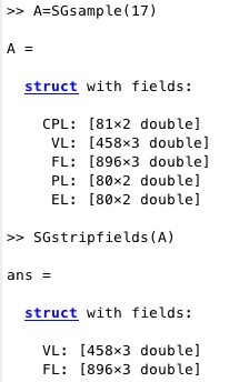 |
% SGstripfields(SG) - remove unneccessary fields in SG structs % (by Tim Lueth, VLFL-Lib, 2015-FEB-20 as class: AUXILIARY PROCEDURES) % % removes CPL,PL,EL (Status of: 2017-03-20) % % See also: SGsample % % SG=SGstripfields(SG) % === INPUT PARAMETERS === % SG: Solid Geoemtry % === OUTPUT RESULTS ====== % SG: Solid Geoemtry % |
VLplotmotion(VL,i)- draws position, speed and acceleration of a VL |
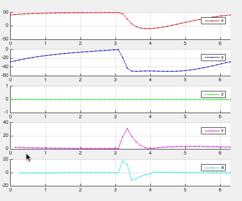 |
% VLplotmotion(VL,i) - draws position, speed and acceleration of a VL % (by Tim Lueth, VLFL-Lib, 2015-FEB-16 as class: KINEMATICS AND FRAMES) % % VLplotmotion(VL,[i]) % === INPUT PARAMETERS === % VL: Vertex list % i: optional angle list % |
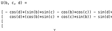
exp_2015_02_14- Experiment that shows the symbolic equation solution of a 4-Bar-Linkage |
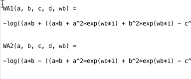 |
% exp_2015_02_14 - Experiment that shows the symbolic equation solution of a 4-Bar-Linkage % (by Tim Lueth, VLFL-Lib, 2015-FEB-13 as class: EXPERIMENTS) % % This Matlab script/fnctn shows how the analytical solution for the % forward kinematics of a Four-Bar-Linkage can be calcuated. Typically % the final result is used later for numerical fnctn, i.e. the calculated % symbolic equation is used as code line in a fnctn such as % 'fourBarLinkage' (Status of: 2015-02-18) % % Introduced first in SolidGeometry 2.1 % % See also: fourBarLinkage % % exp_2015_02_14 % % See also: fourBarLinkage % % % Copyright 2015-2018 Tim C. Lueth |
fourBarLinkage(a,b,c,d,wb,k1,k2)- multi purpose function for a 4-Bar-Linkage |
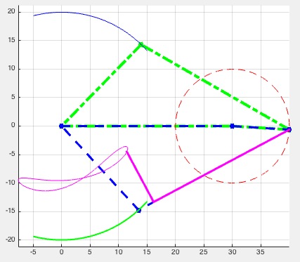 |
% fourBarLinkage(a,b,c,d,wb,k1,k2) - multi purpose fnctn for a 4-Bar-Linkage % (by Tim Lueth, VLFL-Lib, 2015-FEB-13 as class: KINEMATICS AND FRAMES) % % The core of this fnctn are the two analytical solutions for the % calculation of the closed 4-Bar-linkage angle. The fnctn calculates for % given link length a, b, c, d and an angle for phi-b, the two solutions % for closing the linkage and returns the solution points % without an output parameter the configuration is plotted. % without input parameter wb, a drawing is created to explain the linkage % Gestell = Ground % Kurbel = Crank % Koppel = Coupler % Schwinge = Follower % (Status of: 2018-06-02) % % Introduced first in SolidGeometry 2.1 % % See also: exp_2015_02_14, exp_2013_06_15, exp_2013_06_16, fourbarlinkage % % [C,s,D1,D2,wb,wa1,wa2]=fourBarLinkage(a,b,c,d,[wb,k1,k2]) % === INPUT PARAMETERS === % a: ground distance; alternative Point 1 % b: crank length; alternative Point 2 % c: coupler length; alternative Point 3 % d: Follower length; alternative Point 4 % wb: rotation angle at a/b % k1: C+k1*(D1-C) % k2: orthogonal to k1 in mm % === OUTPUT RESULTS ====== % C: Point C % s: solution exist or not % D1: Point D1 % D2: Point D2 % wb: rotation angle at a/b % wa1: rotation angle at a/d (solution 1) % wa2: rotation angle at a/d (solution 2) % % EXAMPLE: To see the use simply try % fourBarLinkage (30,40,30,20); % fourBarLinkage (30,40,30,20,[],0.5); % fourBarLinkage (30,10,30,20,[],0.5); % % See also: exp_2015_02_14, exp_2013_06_15, exp_2013_06_16, fourbarlinkage % % % Copyright 2015-2018 Tim C. Lueth |
exp_2015_02_13- shows the symbolic equation solution for a three bar linkage |
 |
% exp_2015_02_13 - shows the symbolic equation solution for a three bar % linkage % (by Tim Lueth, , 2015-FEB-13 as class: EXPERIMENTS) % % Mainly for educational use! % (Status of: 2015-02-18) % % exp_2015_02_13 % |
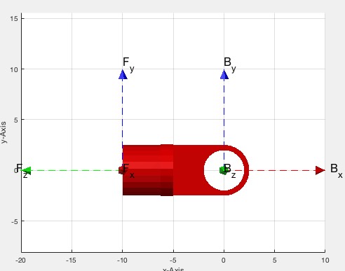
KMchain(KM,chain)- calculates a kinematic structure from a given frame chain |
 |
% KMchain(KM,chain) - calculates a kinematic structure from a given frame % chain % (by Tim Lueth, VLFL-Lib, 2015-FEB-10 as class: KINEMATICS AND FRAMES) % % KM=KMchain(KM,chain) % === INPUT PARAMETERS === % KM: Kinematic model {SG,'Name',HT-Matrix} % chain: string 'A.A-A.B-' % === OUTPUT RESULTS ====== % KM: Kinematic model with adjusted Frames KM{:,3} % % EXAMPLE: Show a robot example: % % |
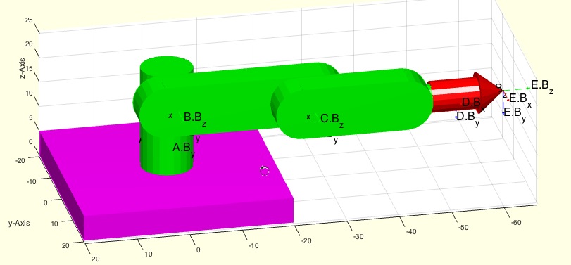
KMplot (KM)- plots all parts of a kinematic model |
 |
% KMplot (KM) - plots all parts of a kinematic model % (by Tim Lueth, VLFL-Lib, 2015-FEB-10 as class: KINEMATICS AND FRAMES) % % A kinematic model is a cell list {nx3} of the format { % % vertex list (VL) and facet list (FL) and a cell list of 4x4 % Frame-matrices (T) and a cell list of Frame-name-strings (Tname). % (Status of: 2015-02-10) % % KMplot(KM) % === INPUT PARAMETERS === % KM: Kinematic model % |
KMT(KM,N);- returns a HT-Matrix from a kinematic model |
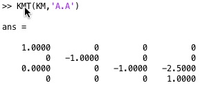 |
% KMT(KM,N); - returns a HT-Matrix from a kinematic model % (by Tim Lueth, VLFL-Lib, 2015-FEB-09 as class: KINEMATICS AND FRAMES) % % A kinematik model currently consists of a list of solids an a list of % strings that can be used to identify the solid in the list. % An error occurs if either the solid name is not existing in the model % or the frame (Status of: 2015-02-09) % % T=KMT(KM,N); % === INPUT PARAMETERS === % KM: Kinematic Model {Solid ' Name'} % N: Name "Solid.Frame" % === OUTPUT RESULTS ====== % T: HT Matrix % |
exp_2015_02_09- EXPERIMENT to show a serial kinematic chain |
 |
% exp_2015_02_09 - EXPERIMENT to show a serial kinematic chain % (by Tim Lueth, VLFL-Lib, 2015-FEB-09 as class: EXPERIMENTS) % % exp_2015_02_09 % |
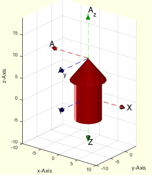
SGT(SGN,N,SN)- returns a called HT-Frame from a solid's struct |
 |
% SGT(SGN,N,SN) - returns a called HT-Frame from a solid's struct % (by Tim Lueth, VLFL-Lib, 2015-FEB-03 as class: KINEMATICS AND FRAMES) % % ======================================================================= % OBSOLETE (2018-07-29) - USE 'SGTget, SGTplot' INSTEAD % ======================================================================= % % Will be removed in future release. Use SGTget instead % if no output parameter is specified, the solid is plotted including the % frames (Status of: 2018-07-29) % % Introduced first in SolidGeometry 2.1 % % See also: [ SGTget, SGTplot ] ; SGTget, SGTset, SGTplot, SGTremove, % SGTui % % [T,a]=SGT(SGN,[N,SN]) % === INPUT PARAMETERS === % SGN: Solid Geoemtry (VL,FL,TName,T) % N: String % SN: Name of Solid Geoemtry for plotting % === OUTPUT RESULTS ====== % T: Transformation matrix % a: index if Frame in Frame cells list % % EXAMPLE: % loadweb JACO_robot.mat; % SGfigure; view(-30,30); SGTplot(JC0,'','A') % % See also: [ SGTget, SGTplot ] ; SGTget, SGTset, SGTplot, SGTremove, % SGTui % % % Copyright 2015-2018 Tim C. Lueth |
SGTremove(SG,N)- removes a transformation frame from a solid geometry |
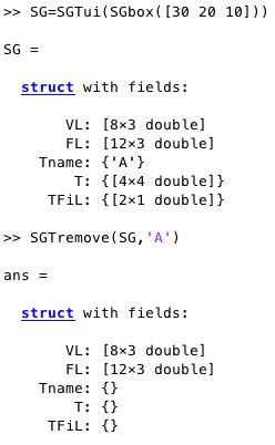 |
% SGTremove(SG,N) - removes a transformation frame from a solid geometry % (by Tim Lueth, VLFL-Lib, 2015-FEB-01 as class: KINEMATICS AND FRAMES) % % to reduce problems with wrong parameter calls, only the name 'all' % should remove all frames of the solid. % Anyway, currently also the call without any name parameter (nargin==1) % will remove all frames; (Status of: 2017-04-18) % % Introduced first in SolidGeometry 2.1 % % See also: SGTget, SGTset, SGTplot, SGTui % % SG=SGTremove(SG,N) % === INPUT PARAMETERS === % SG: SG (VL/FL plus Tname, T, TFiL) % N: string with name of Frame; 'all' removes all frames % === OUTPUT RESULTS ====== % SG: SG without named frame % % EXAMPLE: Set and remove a frame % SG=SGTui(SGbox([30 20 10])), SGTremove(SG,'A') % % See also: SGTget, SGTset, SGTplot, SGTui % % % Copyright 2015-2017 Tim C. Lueth |
SGTui(SG,N,fe,FS,Rz)- returns a HT matrix for a manuel selected union space |
 |
% SGTui(SG,N,fe,FS,Rz) - returns a HT matrix for a manuel selected union space % (by Tim Lueth, VLFL-Lib, 2015-FEB-01 as class: KINEMATICS AND FRAMES) % % This is a user interface for manually selecting union patches or tips % (vertices) to generate frames for linking HT matrices to the solid % geometries. It support 3 types of frames % a) tips % b) planar surfaces % c) spherical surfaces with feature edges % SGT changed in SG-Lib 3.9 and supports also centers of circular borders % (Status of: 2017-07-21) % % Introduced first in SolidGeometry 2.1 % % See also: SGTget, SGTset, SGTplot, SGTremove, VLFLsurfaceofSGT % % [SGN,T,h,Rorg]=SGTui(SG,[N,fe,FS,Rz]) % === INPUT PARAMETERS === % SG: Solid Geometry % N: Name of the new/replaced Frame % fe: feature edge angle; default 0.08; use 1 for freeform surfaces % FS: Optional string selector for center points such as 'R1' % Rz: Optional Rz rotation angle % === OUTPUT RESULTS ====== % SGN: New SG with Tname, T, TFiL % T: Transformation matrix % h: handle to graphic % Rorg: % % EXAMPLE: load AIM_SGrobot; SG3=SGTremove(SG3,'all'); % SG3=SGTui(SG3,[],0.3) % % See also: SGTget, SGTset, SGTplot, SGTremove, VLFLsurfaceofSGT % % % Copyright 2015-2017 Tim C. Lueth |
SGmelting(SG)- returns a surface model without intrusion of solids |
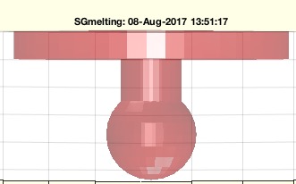 |
% SGmelting(SG) - returns a surface model without intrusion of solids % (by Tim Lueth, VLFL-Lib, 2015-FEB-01 as class: 3D MANUFACTURING) % % ======================================================================= % OBSOLETE (2017-08-08) - USE FAMILY 'SGsurfacemeltbool' INSTEAD % ======================================================================= % % This fnctn is necessary if slicer programs as part of the 3D % manufacturing process are unable to handle intrusions of separated % surface models within one STl-File. % It is slow since it uses intensively SGbool (Status of: 2015-02-11) % % Introduced first in SolidGeometry 2.1 % % See also: [ SGsurfacemeltbool ] ; SGbool % % SGN=SGmelting(SG) % === INPUT PARAMETERS === % SG: Surface model that contains separated surfaces % === OUTPUT RESULTS ====== % SGN: % % See also: [ SGsurfacemeltbool ] ; SGbool % % % Copyright 2015-2017 Tim C. Lueth |
TR3mountingfaces(TR3,fi,fe)- finds connected facets with same normal vector |
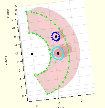 |
% TR3mountingfaces(TR3,fi,fe) - finds connected facets with same normal vector % (by Tim Lueth, VLFL-Lib, 2015-FEB-01 as class: SURFACES) % % Powerful but slow/recursive fnctn to detect points that defined planar % and spherical surfaces. % Auxiliary fnctn developed originally for and used in SGTui (Status of: % 2018-08-01) % % Introduced first in SolidGeometry 2.1 % % See also: TR3mountingfaces, MLofSG, SGTui % % [FIL,nv,FnL,NnL,RL,CVL,TR3]=TR3mountingfaces(TR3,fi,[fe]) % === INPUT PARAMETERS === % TR3: Surface triangulation of a solid % fi: singe facet index % fe: feature edge angle; default is 0 % === OUTPUT RESULTS ====== % FIL: all facets connected to first facet with the same normal vector % nv: normal vector of this facet % FnL: all neigbor facets of FIL. WARNING: Always empty if fe>0 % NnL: normal vector angle difference to nv of FnL % RL: Radial list created by CVLdimclassifier % CVL: CLosed Vertex list used for CVLdimclassifier % TR3: TR# is case that an SG was used as input parameter % % EXAMPLE: % SG=SGtransR(SGsample(25),rot(pi/6,0,pi/2)); % TR3=triangulation(SG.FL,SG.VL); % [a,b,c,d,RL,CVL]=TR3mountingfaces(TR3,60,1); % SGfigure; h=SGplot(SG); setplotlight(h,'r',0.1); CVLplot(CVL); % VLplot(RL(:,1:3),'k*',5); % % See also: TR3mountingfaces, MLofSG, SGTui % % % Copyright 2015-2018 Tim C. Lueth |
SGpacking(SGC,dim,dist,ez,turn)- returns a package of all solids of a cell list |
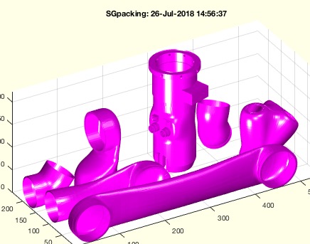 |
% SGpacking(SGC,dim,dist,ez,turn) - returns a package of all solids of a cell list % (by Tim Lueth, VLFL-Lib, 2015-JAN-31 as class: 3D MANUFACTURING) % % arranges the solids in a cell list of solids in a specified volume % (Status of: 2018-08-01) % % Introduced first in SolidGeometry 2.1 % % See also: SGsurfaces, SGanalyzeGroupParts, SGboxing, SGboxpacking, % SGpatternXYZ, SGcopyrotZ, SGarrangeSG, SGarrangeSGC, SGCaddSGn, SGCaddSG % % [SGN,SG]=SGpacking(SGC,[dim,dist,ez,turn]) % === INPUT PARAMETERS === % SGC: Cell list of solid geometries % dim: dimension of package, default is [85 65 100]; % dist: minimal distance between solids; default is 1; % ez: optional ez vector for turning limitation; default is empty; % turn: true== turn to flat; false==unchanged orientation; default is true % === OUTPUT RESULTS ====== % SGN: Packed solid geometry as one solid % SG: Packed solid geometry as cell list % % EXAMPLE: % loadweb JACO_robot.mat; SGpacking(JACO,[600 500 500],10,'',false) % loadweb JACO_robot.mat; SGpacking(JACO,[600 500 500],10,'',true) % % See also: SGsurfaces, SGanalyzeGroupParts, SGboxing, SGboxpacking, % SGpatternXYZ, SGcopyrotZ, SGarrangeSG, SGarrangeSGC, SGCaddSGn, SGCaddSG % % % Copyright 2015-2018 Tim C. Lueth |
binpacking3D(LAY,BOXL,grid)- returns a straight forward bin packing |
 |
% binpacking3D(LAY,BOXL,grid) - returns a straight forward bin packing % (by Tim Lueth, VLFL-Lib, 2015-JAN-31 as class: AUXILIARY PROCEDURES) % % h/2 is a good estimation for a layout size [h/2 h/2 300] if object % height differs % (Status of: 2015-01-31) % % [BOXL,h]=binpacking3D([LAY,BOXL,grid]) % === INPUT PARAMETERS === % LAY: Layout dimensions; default [100,60,80] % BOXL: nx4 [index size-x size-y size-z] % grid: grid size; default is 1 mm % === OUTPUT RESULTS ====== % BOXL: nx4 [index pos-x pos-y pos-z] % h: estimation of a square side length if all bin have the same heigth % % EXAMPLE: Just enter: binpacking3D % |
PLtransT(PL,T)- rotates and moves a point list nx2 |
 |
% PLtransT(PL,T) - rotates and moves a point list nx2 % (by Tim Lueth, VLFL-Lib, 2015-JAN-30 as class: ANALYTICAL GEOMETRY) % % Introduced first in SolidGeometry 2.1 % % See also: PLtransP, PLtransR, PLtrans, PLtrans0, PLtrans1, PLtransC % % PL=PLtransT(PL,T) % === INPUT PARAMETERS === % PL: Point list nx2 % T: Transformation matrix 2x3 or 3x3 % === OUTPUT RESULTS ====== % PL: Point list nx2 % % See also: PLtransP, PLtransR, PLtrans, PLtrans0, PLtrans1, PLtransC % % % Copyright 2015-2018 Tim C. Lueth |
PLtrans1(PL)- returns a point list moved into the first quadrant |
 |
% PLtrans1(PL) - returns a point list moved into the first quadrant % (by Tim Lueth, VLFL-Lib, 2015-JAN-30 as class: ANALYTICAL GEOMETRY) % % Introduced first in SolidGeometry 2.1 % % See also: PLtransP, PLtransR, PLtrans, PLtrans0, PLtransT, PLtransC % % PL=PLtrans1(PL) % === INPUT PARAMETERS === % PL: Point list nx2 % === OUTPUT RESULTS ====== % PL: Point list nx2 % % See also: PLtransP, PLtransR, PLtrans, PLtrans0, PLtransT, PLtransC % % % Copyright 2015-2018 Tim C. Lueth |
PLtrans0(PL)- returns an origin centered point list |
 |
% PLtrans0(PL) - returns an origin centered point list % (by Tim Lueth, VLFL-Lib, 2015-JAN-30 as class: AUXILIARY PROCEDURES) % % Introduced first in SolidGeometry 2.1 % % See also: PLtransP, PLtransR, PLtrans, PLtrans1, PLtransT, PLtransC % % PL=PLtrans0(PL) % === INPUT PARAMETERS === % PL: Point list nx2 % === OUTPUT RESULTS ====== % PL: Point list nx2 % % See also: PLtransP, PLtransR, PLtrans, PLtrans1, PLtransT, PLtransC % % % Copyright 2015-2018 Tim C. Lueth |
PLtrans(PLin,T)- multi transformation modes for a point list |
 |
% PLtrans(PLin,T) - multi transformation modes for a point list % (by Tim Lueth, VLFL-Lib, 2015-JAN-30 as class: ANALYTICAL GEOMETRY) % % Does currently not support a cells of points list % Combines PLtrans0, PLtrans1, PLtransP, PLtransR, PLtransT depending on % the transformation value % % (Status of: 2018-07-31) % % Introduced first in SolidGeometry 2.1 % % See also: PLtransP, PLtransR, PLtrans0, PLtrans1, PLtransT, PLtransC % % [PLout,varargout]=PLtrans(PLin,T) % === INPUT PARAMETERS === % PLin: Point list nx2 % T: Transformation Value, Vector, or Matrix % === OUTPUT RESULTS ====== % [Lout,varargout]=PLtrans(PLin,T) % % if size(T,1)==1 && size(T,2)==1 % if T==0]: Point list nx2 % [Lout,varargout]=PLtrans(PLin,T) % % if size(T,1)==1 && size(T,2)==1 % if T==0]: not used yet % % EXAMPLE: try: % PLtrans(PLcircle(10),[rotdeg(40) [10;0]]) % PLtrans(rand(20,2),0) % PLtrans(rand(20,2),1) % PLtrans(rand(20,2),[10, 0]) % PLtrans(rand(20,2),[10; 0]) % PLtrans(rand(20,2),rot(pi/3)) % PLtrans(rand(20,2),rotdeg(40)) % PLtrans(rand(20,2),[rotdeg(40) [10;0]]) % % See also: PLtransP, PLtransR, PLtrans0, PLtrans1, PLtransT, PLtransC % % % Copyright 2015-2018 Tim C. Lueth |
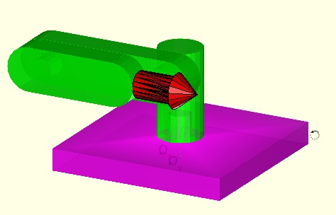
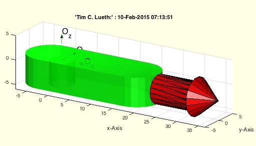
AIM_Robot- returns a solid geometry for a robot used in AIM lectures |
 |
% AIM_Robot - returns a solid geometry for a robot used in AIM lectures % (by Tim Lueth, VLFL-Lib, 2015-JAN-30 as class: MODELING PROCEDURES) % % exatly the same as exp_2015_01_30 (Status of: 2015-06-08) % % SGrobot=AIM_Robot % === OUTPUT RESULTS ====== % SGrobot: Solid Geometry of a printable Robot for AIM % |
exp_2015_01_30- returns a solid geometry for a robot used in AIM lectures |
 |
% exp_2015_01_30 - returns a solid geometry for a robot used in AIM % lectures % (by Tim Lueth, VLFL-Lib, 2015-JAN-30 as class: MODELING PROCEDURES) % % SGrobot=exp_2015_01_30 % === OUTPUT RESULTS ====== % SGrobot: Solid Geometry of a printable Robot for AIM % |
gets(allargins,paramstr,tab)- processes automatically the varargins of a function |
 |
T2plot(p,c,w,N,N)- plots a HT matrix as straight line vector |
 |
% T2plot(p,c,w,N,N) - plots a HT matrix as straight line vector % (by Tim Lueth, VLFL-Lib, 2015-JAN-27 as class: VISUALIZATION) % % See also: pplot, lplot, tfplot, tlplot, slplot, plotTP, plotL, plotT % % T2plot(p,[c,w,N,N]) % === INPUT PARAMETERS === % p: Point or % c: color % w: width % N: String for name % N: % |
slplot (p,ez,c,w,l,d)- straight line plot |
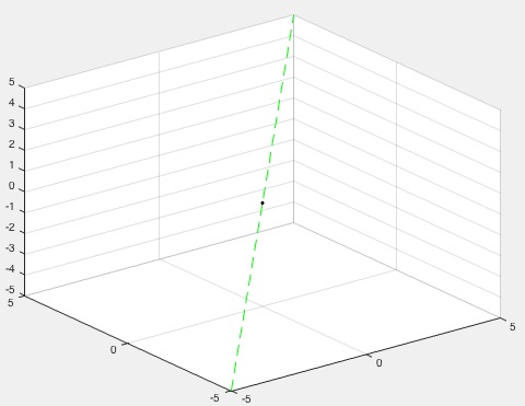 |
% slplot (p,ez,c,w,l,d) - straight line plot % (by Tim Lueth, VLFL-Lib, 2015-JAN-26 as class: VISUALIZATION) % % See also: getvar, pplot, lplot, tfplot, tlplot, plotTP, plotL, plotT, % T2Plot % % slplot(p,[ez,c,w,l,d]) % === INPUT PARAMETERS === % p: starting point % ez: direction if straight line % c: line color % w: line width; default is 1 % l: line length; default is 10 % d: color of the starting point % === PROPERTY NAMES ===== % 'color' : Color of the straight line; default is 'r--' % 'point' : Color of the start point; default is 'k.' % 'length' : Length of the line; default is 10 % 'lineWidth' : Width of the straight line; default is 1 % 'color' : % 'point' : % 'length' : % 'lineWidth' : % % EXAMPLE: Plot a green straight line % slplot([0 0 0],[1 1 1],'color','g--') % |
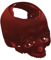
VMpseudo3D(V,lim,maxc,s)- returns an 2D image of pseudo 3D rendered surface |
 |
% VMpseudo3D(V,lim,maxc,s) - returns an 2D image of pseudo 3D rendered surface % (by Tim Lueth, VLFL-Lib, 2015-JAN-26 as class: VOXELS) % % Use matlab fnctns permute and flip and view to produce the desired % output (Status of: 2017-02-16) % % See also: VM, VMimage, VMimrot90, VMmontage, VMplot, VMreaddicom, % VMreaddicomdir, VMuidicom % % I=VMpseudo3D(V,lim,[maxc,s]) % === INPUT PARAMETERS === % V: Voxel model % lim: surface intensity value % maxc: maximum used color; default is 4095 % s: cut value: start to display the real slice values; default is 0 % === OUTPUT RESULTS ====== % I: Image % % EXAMPLE: % I=VMpseudo3D(permute(V,[2 3 1]),1600,4095,100); % imshow(I,[0 4095]); axis square, view (-90,90); show % close all; VMpseudo3D(flip(permute(V,[3 2 1]),1),1400,'',200); % |
VMmontage(V)- plots all images of an image stack into one figure |
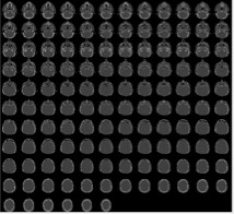 |
% VMmontage(V) - plots all images of an image stack into one figure % (by Tim Lueth, VLFL-Lib, 2015-JAN-24 as class: VOXELS) % % Based on Matlab fnctn montage (Status of: 2017-04-02) % % See also: VMimage, VMintensityscale, VMresize, VMimrot90, VMplot, % VMpseudo3D, VMreaddicom, VMreaddicomdir, VMuidicom % % h=VMmontage(V) % === INPUT PARAMETERS === % V: Voxel model % === OUTPUT RESULTS ====== % h: handle of image % |
VLscatter(VL,C,n)- plots a vertex list with a corresponding image intensity list |
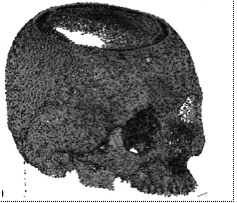 |
% VLscatter(VL,C,n) - plots a vertex list with a corresponding image intensity list % (by Tim Lueth, VLFL-Lib, 2015-JAN-22 as class: VOXELS) % % See also: VLplot, VLofVM % % h=VLscatter(VL,C,n) % === INPUT PARAMETERS === % VL: Vertex list % C: Intensity List (Hounsfield) % n: step size for vertex selection % === OUTPUT RESULTS ====== % h: handle to plot % % EXAMPLE: Scatter a Voxelmodel % VLscatter(VLofVM(V>1600),V(find(V>1600)),10); % |
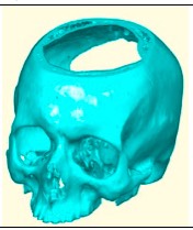
VLFLofVMmarchcube(V,vs)- returns a surface model by the marching cubes |
 |
% VLFLofVMmarchcube(V,vs) - returns a surface model by the marching cubes % (by Tim Lueth, VLFL-Lib, 2015-JAN-22 as class: VOXELS) % % This fnctn uses the MarchingCubes fnctn from Matlab Central written by % Peter Hammer in 2011 based on the Octave fnctn written by Martin Helm % (www.mhelm.de/octave/m/marching_cube.m) in 2009. It contains also code % from Oliver Woodford for removing duplicated vertices. (Status of: % 2017-02-16) % % See also: VLFLofVMdelaunay % % [VL,FL]=VLFLofVMmarchcube(V,[vs]) % === INPUT PARAMETERS === % V: Logical Volume Model % vs: voxel size, optional % === OUTPUT RESULTS ====== % VL: Vertex list % FL: Facet list % % EXAMPLE: [V,vs]=VMreaddicomdir('AIM_DICOMFILES'); % [VL,FL]=VLFLofVMmarchcube((V>400)&(V<1100),vs); % VLFLfigure(VL,FL); % |
VLFLofVMdelaunay(V,vs,s)- returns a surface model for a delaunay reconstructed volume model |
 |
% VLFLofVMdelaunay(V,vs,s) - returns a surface model for a delaunay reconstructed volume model % (by Tim Lueth, VLFL-Lib, 2015-JAN-20 as class: VOXELS) % % See also: VLFLofVMdelaunay, VLFLofVMmarchcube % % [VL,FL,TR4]=VLFLofVMdelaunay(V,[vs,s]) % === INPUT PARAMETERS === % V: Voxel Model (~=0 is reconstruction) % vs: voxel size, optional % s: step size % === OUTPUT RESULTS ====== % VL: Vertex list % FL: Facet list % TR4: Delaunay tetrahedron model % |
TR2ofimage(I,t)- returns a Delaunay triangulation for a grayscale image |
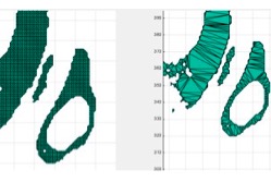 |
% TR2ofimage(I,t) - returns a Delaunay triangulation for a grayscale image % (by Tim Lueth, VLFL-Lib, 2015-JAN-20 as class: VOXELS) % % Type = 0 => triangulation contains all pixels and pixel facets % Type = 1 => triangulation contains only triangulated boundary facets % % WARNING: This procedure contains a real Matlab coding bug: If the two % lines of procedure TR2reduce are directly inserted in the code, an % error occurs by the isInterior procedure that is not explainable. % (Status of: 2015-01-20) % % TR2=TR2ofimage(I,[t]) % === INPUT PARAMETERS === % I: Image nxm % t: type of triangulation (default is 1) % === OUTPUT RESULTS ====== % TR2: delaunay triangulation % % EXAMPLE: Analyze dicom images: % subplot (1,2,1); TR2ofimage (I1>1400,0); % subplot (1,2,2); TR2ofimage (I1>1400,1); % |
TR3ofVM(V,vs,s)- returns a |
 |
% TR3ofVM(V,vs,s) - returns a % (by Tim Lueth, VLFL-Lib, 2015-JAN-20 as class: VOXELS) % % See also: VLFLofVMdelaunay, VLFLofVMmarchcube % % [TR4,TR3]=TR3ofVM(V,[vs,s]) % === INPUT PARAMETERS === % V: % vs: % s: % === OUTPUT RESULTS ====== % TR4: % TR3: % |
VM(I)- returns a matrix of reduced size if required (squeeze) |
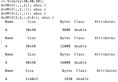 |
% VM(I) - returns a matrix of reduced size if required (squeeze) % (by Tim Lueth, VLFL-Lib, 2015-JAN-19 as class: VOXELS) % % Obsolete fnctn: Better use Matlab fnctn squeeze directly % This is an auxiliary fnctn to take out a nxnxm submatrix from a nxnxm % matrix, since Matlab does not treat nxnxm matrice orthogonal to nxm % matrices. This fnctn is preferable to take out an orthogonal slice or % subvolume from a voxel model. (Status of: 2017-02-16) % % See also: VMimage, VMimrot90, VMmontage, VMplot, VMpseudo3D, % VMreaddicom, VMreaddicomdir, VMuidicom % % I=VM(I) % === INPUT PARAMETERS === % I: Matrix n x n x m % === OUTPUT RESULTS ====== % I: Matrix n x n x m % % EXAMPLE: Different subvolums from a 3D voxel model: % V=zeros(30,40,50); % A=VM(V(:,:,2)); whos A % A=VM(V(:,2,:)); whos A % A=VM(V(2,:,:)); whos A % A=VM(V(2:3,:,4:6)); whos A % |
VLofVM(VM,vs)- returns the voxel coordinates as point list (can be long) |
 |
% VLofVM(VM,vs) - returns the voxel coordinates as point list (can be long) % (by Tim Lueth, VLFL-Lib, 2015-JAN-14 as class: VOXELS) % % % VL=VLofVM(V>0.5); returns all voxel coordinates of V(:,:,:)>0.5 % I=V(V>0.5); contains all voxel intensities for the VL % VL=VLofVM(V>0.5,[0.4 0.4 1]) returns all cartesian coordinates using vs % (Status of: 2017-03-20) % % See also: VLplot, VLscatter, VLofimage % % VL=VLofVM(VM,[vs]) % === INPUT PARAMETERS === % VM: Voxel model (mxmxn) or image stack % vs: optional voxel size % === OUTPUT RESULTS ====== % VL: Vertex list % % EXAMPLE: VL=VLofVM(V(:,:,64)>1400); VLplot(VL,'m.') % [VL,EL,FL]=VLofimage(:,:,64)>1200, 1 , 2); % % [VL,C]=VLofVM(V(:,:,1:10)>1400); C=V(V(:,:,1:10)>1400); % |
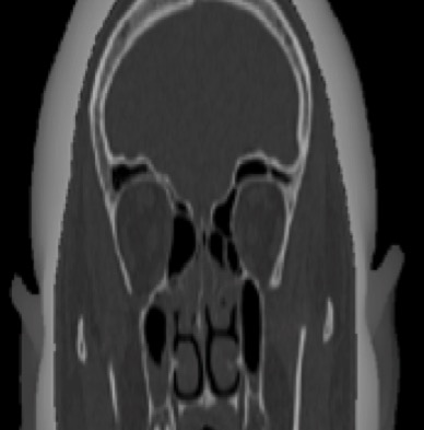
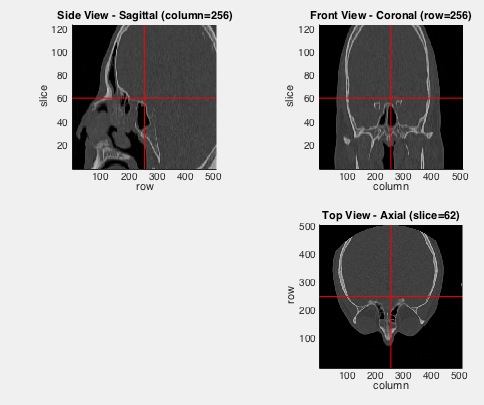
VMimage (IM,p)- returns three crosssectional views of an image stack (voxel model) |
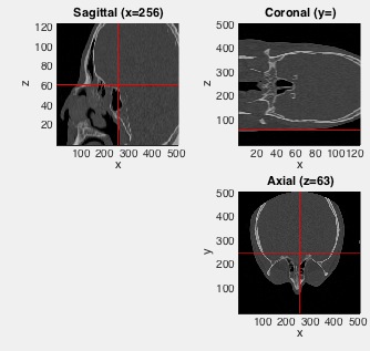 |
% VMimage (IM,p) - returns three crosssectional views of an image stack (voxel model) % (by Tim Lueth, NAV-Lib, 2015-JAN-14 as class: VISUALIZATION) % % By default the center of the image is used to create the three % crosssectional views. (Status of: 2017-04-15) % % Introduced first in SolidGeometry 2.1 % % See also: VM, VMimrot90, VMmontage, VMplot, VMpseudo3D, VMreaddicom, % VMreaddicomdir, VMuidicom % % VMimage(IM,[p]) % === INPUT PARAMETERS === % IM: 3D Matrix % p: optional point of interest (row, column, slice) % % See also: VM, VMimrot90, VMmontage, VMplot, VMpseudo3D, VMreaddicom, % VMreaddicomdir, VMuidicom % % % Copyright 2015-2017 Tim C. Lueth |
VMimrot90(I)- returns an 90 degree rotated image (nxm) or image stack (nxmxk) |
 |
% VMimrot90(I) - returns an 90 degree rotated image (nxm) or image stack (nxmxk) % (by Tim Lueth, VLFL-Lib, 2015-JAN-13 as class: VOXELS) % % +90 degree: fliplr(I') % 180 degree: flipud(I) % -90 degree: flipud(I') (Status of: 2017-02-16) % % See also: VM, VMimage, VMmontage, VMplot, VMpseudo3D, VMreaddicom, % VMreaddicomdir, VMuidicom % % NI=VMimrot90(I) % === INPUT PARAMETERS === % I: image or image stack % === OUTPUT RESULTS ====== % NI: new image or image stack % |
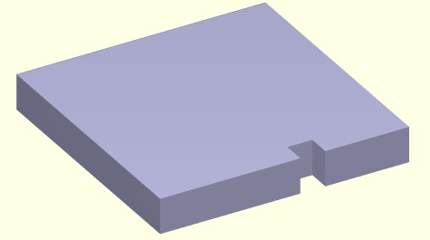
SGintersectFacetPoints(A,B)- calculates a list of crossing facet pairs and crossing points of 2 solids |
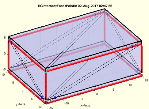 |
% SGintersectFacetPoints(A,B) - calculates a list of crossing facet pairs and crossing points of 2 solids % (by Tim Lueth, VLFL-Lib, 2015-JAN-12 as class: SURFACES) % % This fnctn is now (2017-Aug) 5 times faster than the fastest % MatlabCentral implementation mesh2mesh. Therefor fnctn VLcrossingSG % should be based on SGintersectFacetPoints in future for collision % checks. % This fnctn is an elementary part of SGbool1-SGbool3 and was isolated % and improved for SGbool4 in 2017-07-31. % The 6th row is may be obsolete, since it is not used in % VLFLinsertFacetPoints % The resulting format of NPL is: % col 01: facet of A % col 02: facet of B % col 03-05: crossing point % col 06: intersection information % col 06: sign is inside/out 1..3 is % cal 06: value ==> 1..3 means 1st facet egde; 0.1..0.3 means 2nd face % edge % (Status of: 2017-08-03) % % Introduced first in SolidGeometry 2.1 % % See also: crossingfacets2VLFL, cross2F, intersectstriangle, % VLFLinsertFacetPoints % % [NPL,IEL]=SGintersectFacetPoints(A,B) % === INPUT PARAMETERS === % A: Solid A % B: Solid B % === OUTPUT RESULTS ====== % NPL: New point list % IEL: edge list % % EXAMPLE: % A=SGbox([30,20,10]); B=SGtransP(A,[1 2 3]); % SGintersectFacetPoints(A,B) % % % See also: crossingfacets2VLFL, cross2F, intersectstriangle, % VLFLinsertFacetPoints % % % Copyright 2015-2017 Tim C. Lueth |
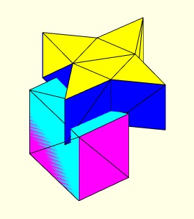
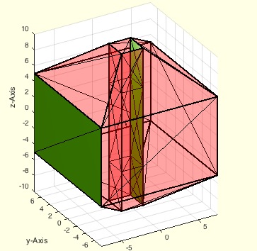
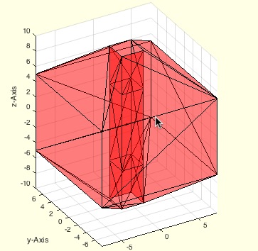
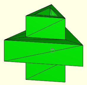
VLFLinsertFacetPoints(VLA,FLA,NPL)- This function retesselates all surfaces of a solid by inserting points into existing facets |
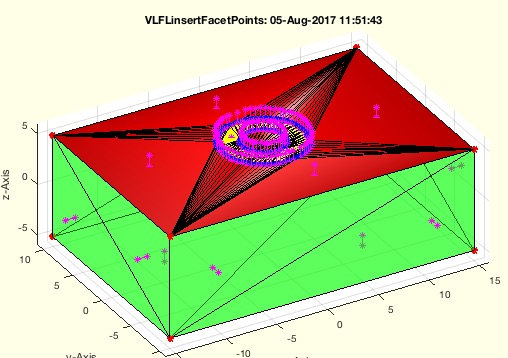 |
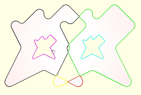
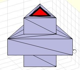
% VLFLinsertFacetPoints(VLA,FLA,NPL) - This fnctn retesselates all surfaces of a solid by inserting points into existing facets % (by Tim Lueth, VLFL-Lib, 2015-JAN-12 as class: SURFACES) % % This fnctn is an elementary part of SGbool1-SGbool3 and was isolated % for SGbool4 in 2017-08-02 % It is not enough just to add the points to a triangle but also it is % necessary to add edges inside of the facet for each cutting edge! % Otherwise it is not possible to reconnect the two separated handled % Solids! % The final result are THREE retesselate facet list: NFL and SFL and UFL % The orientation of the faces of SFL are changed. (Status of: 2017-08-06) % % Introduced first in SolidGeometry 2.1 % % See also: SGintersectFacetPoints, crossingfacets2VLFL, cross2F, % intersectstriangle % % [XVL,XFIL,NFL,SFL,UFL]=VLFLinsertFacetPoints(VLA,FLA,NPL) % === INPUT PARAMETERS === % VLA: Solid A % FLA: Solid B % NPL: New Point List created by SGintersectFacetPoints % === OUTPUT RESULTS ====== % XVL: Original point list plus additional points % XFIL: Facet index list of original facets that were changed % NFL: Facets that belong completely to crossing points (red) % SFL: Facets that connect untouched points and crossing points (yellow) % UFL: Facets that are not touched (green) % % EXAMPLE: % A=SGbox([30,20,10]); B=SGtransP(A,[1 2 3]); % SGintersectFacetPoints(A,B); NPL=ans % A=SGbox([30,20,10]); B=SGofCPLz([PLcircle(4);NaN % NaN;PLcircle(2)],10);SGintersectFacetPoints(A,B); NPL=ans % VLFLinsertFacetPoints(A.VL,A.FL,NPL) % VLFLinsertFacetPoints(B.VL,B.FL,NPL(:,[2 1 3:end])) % % See also: SGintersectFacetPoints, crossingfacets2VLFL, cross2F, % intersectstriangle % % % Copyright 2015-2017 Tim C. Lueth |
exp_2015_01_10c (bo)- |
 |
% exp_2015_01_10c (bo) - % (by Tim Lueth, VLFL-Lib, 2015-JAN-11 as class: EXPERIMENTS) % % exp_2015_01_10c([bo]) % === INPUT PARAMETERS === % bo: % |
SGbool3(flag,A,B)- returns the result of a boolean operation on two solids |
 |
% SGbool3(flag,A,B) - returns the result of a boolean operation on two % solids % (by Tim Lueth, VLFL-Lib, 2015-JAN-11 as class: SURFACES) % % First version that works completely correct. Next step is % retesselation. IgtG % A= A without B % B= B without A % += A combined with B % x= A intersected with B % There is one problem with concave surfaces (Status of: 2015-01-11) % % SGX=SGbool3(flag,A,B) % === INPUT PARAMETERS === % flag: Boolean operator ('AB+x') % A: Solid A (VL/FL) % B: Solid B (VL/FL) % === OUTPUT RESULTS ====== % SGX: resulting surface geometry % |
exp_2015_01_11 (SGA,bo)- EXPRIMENT TO drill through STL-FIles using SGbool |
 |
% exp_2015_01_11 (SGA,bo) - EXPRIMENT TO drill through STL-FIles using SGbool % (by Tim Lueth, VLFL-Lib, 2015-JAN-11 as class: EXPERIMENTS) % % exp_2015_01_11(SGA,[bo]) % === INPUT PARAMETERS === % SGA: Solid Geoemtry % bo: % |
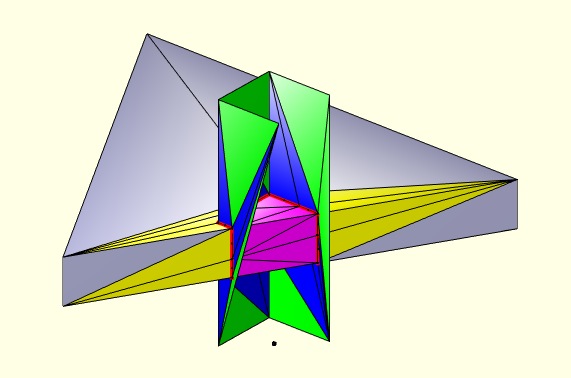
FLorder(FL)- returns a shifted and ordered facet list |
 |
% FLorder(FL) - returns a shifted and ordered facet list % (by Tim Lueth, VLFL-Lib, 2015-JAN-11 as class: AUXILIARY PROCEDURES) % % The facet list is rotated line by line so that the smallest vertex % index is in the left column. % % In contrast to FLshift, by using FLorder the facet list is sorted by % increasing numbers of column sortrows(FL,[1 2 3]). (Status of: % 2017-02-21) % % See also: ELorder, FLseparate, TRorder, SGorder, SGseparate % % FL=FLorder(FL) % === INPUT PARAMETERS === % FL: Original facet list % === OUTPUT RESULTS ====== % FL: Final facet list % % EXAMPLE: % FL=[10 20 30; 30 10 20; 20 30 10] % FL=[FL*1.5;FL] % FLorder(FL) % |
exp_2015_01_11 (SGA,bo)- EXPERIMENT that shows the power of SGboo3 |
 |
% exp_2015_01_11 (SGA,bo) - EXPERIMENT that shows the power of SGboo3 % (by Tim Lueth, VLFL-Lib, 2015-JAN-11 as class: EXPERIMENTS) % % exp_2015_01_11(SGA,[bo]) % === INPUT PARAMETERS === % SGA: Solid Geometry % bo: boolean operator % |
exp_2015_01_10 (bo)- EXPERIMENT to the first usable function SGbool |
 |
% exp_2015_01_10 (bo) - EXPERIMENT to the first usable fnctn SGbool % (by Tim Lueth, VLFL-Lib, 2015-JAN-10 as class: EXPERIMENTS) % % exp_2015_01_10([bo]) % === INPUT PARAMETERS === % bo: flag; default is x (intersection) % |
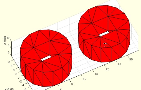
exp_2015_01_08m- EXPERIMENT that tesselates a solid as preparation for cutting |
 |
% exp_2015_01_08m - EXPERIMENT that tesselates a solid as preparation for % cutting % (by Tim Lueth, VLFL-Lib, 2015-JAN-10 as class: SURFACES) % % NPL=exp_2015_01_08m % === OUTPUT RESULTS ====== % NPL: % |
exp_2015_01_08i- EXPERIMENT that tesselates a solid as preparation for cutting |
 |
% exp_2015_01_08i - EXPERIMENT that tesselates a solid as preparation for % cutting % (by Tim Lueth, VLFL-Lib, 2015-JAN-10 as class: SURFACES) % % exp_2015_01_08i % |
SGisInterior(SG,VL)- returns the isInside Flag for a SG and a VL |
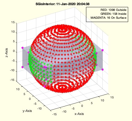 |
% SGisInterior(SG,VL) - returns the isInside Flag for a SG and a VL % (by MATLAB-CENTRAL, VLFL-Lib, 2015-JAN-10 as class: SURFACES) % % Fast checking fnctn for points that are not on the surface. Surface % points belong to the inner points. % Bugs appear if points are at the same position but different z axis. % Could easily be solved. % This fnctn still has some bugs with vertices on the surface of the % solid. See mesh2mesh to learn how to improve VLFLinpolyhedron (Status % of: 2017-01-02) % % See also: mesh2mesh, VLFLinpolyhedron, BBiscollofVL, outboundingbox, % VLcrossingSG, crossingfacets2VLFL % % VIL=SGisInterior(SG,VL) % === INPUT PARAMETERS === % SG: Solid Geoemtry % VL: Vertex list to test % === OUTPUT RESULTS ====== % VIL: Vertex index list % % EXAMPLE: Test the probleatic surface points if this fnctn: % A=SGbox([30,20,10]); % VLcrossingSG(A,SGtrans(A,rotdeg(90))); % VL=VLcrossingSG(A,SGtrans(A,rotdeg(90))); % VL=unique(VL,'rows'); % SGisInterior(A,VL) % % More sucessfull test % A=SGbox([30,20,10]); SGisInterior(A,20*(rand(100,3)-0.5)); % |
VLFLfaceNormal(VL,FL,fi,th)- returns the normal vector of the facet list and cutted (1e-4) length |
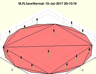 |
% VLFLfaceNormal(VL,FL,fi,th) - returns the normal vector of the facet list and cutted (1e-4) length % (by Tim Lueth, VLFL-Lib, 2015-JAN-09 as class: ANALYTICAL GEOMETRY) % % This is a fnctn to adapt the VLFL syntax to R2014b. % The matlab cross-fnctn of triangualtion results returns calucation % error in size (1e-4) (Status of: 2017-08-14) % % Introduced first in SolidGeometry 2.1 % % See also: VLFLvertexNormal, PLnorm, PLELnorm, PLFLfaceNormal, VLnorm, % VLFLnormf, VLedgeNormal, VLFLfaceAngles % % [NL,AL]=VLFLfaceNormal(VL,FL,[fi,th]) % === INPUT PARAMETERS === % VL: Vertex list n x 3 % FL: Facet list % fi: optional value; facet index (list) % th: % === OUTPUT RESULTS ====== % NL: Normal vector list % AL: Area list; % % EXAMPLE: % [VL,FL]=PLFLofCPLdelaunay(PLcircle(1)); VL=VLaddz(VL); % VLFLfaceNormal(VL,FL) % % See also: VLFLvertexNormal, PLnorm, PLELnorm, PLFLfaceNormal, VLnorm, % VLFLnormf, VLedgeNormal, VLFLfaceAngles % % % Copyright 2015-2018 Tim C. Lueth |
exp_2015_01_08b- EXPERIMENT SCRIPT for testing crossingfacets2VLFL |
 |
% exp_2015_01_08b - EXPERIMENT SCRIPT for testing crossingfacets2VLFL % (by Tim Lueth, VLFL-Lib, 2015-JAN-08 as class: EXPERIMENTS) % % exp_2015_01_08b % |
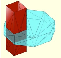
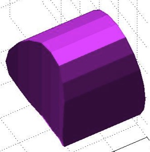
SGcut(SG,z)- Cuts a solid geometry into 2 parts at a defined z-plane |
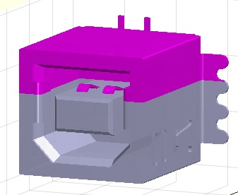 |
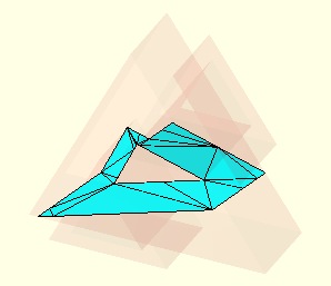
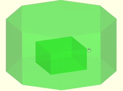
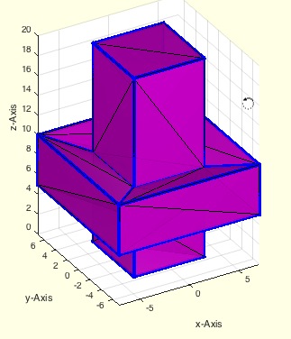
% SGcut(SG,z) - Cuts a solid geometry into 2 parts at a defined z-plane % (by Tim Lueth, VLFL-Lib, 2015-JAN-08 as class: SURFACES) % % returns two solid solids (VL,FL). It is a good programming example how % to use SGslicer. % Without output parameter is shows the cutted parts using VLFLfigure % (Status of: 2017-01-29) % % Introduced first in SolidGeometry 2.1 % % See also: SGcut, SGcut2, SGcutBB, SGcutT % % [SGA,SGB]=SGcut(SG,z) % === INPUT PARAMETERS === % SG: Solid Geometry (VL,FL) % z: z value for slicing or interval [z1 z2] % === OUTPUT RESULTS ====== % SGA: Solid below cutting plane (and above z2) (grey) % SGB: Solid above cutting plane (and in between z2) (magenta) % % EXAMPLE: SGcut (SGsample(7),+10); % % See also: SGcut, SGcut2, SGcutBB, SGcutT % % % Copyright 2015-2018 Tim C. Lueth |
exp_2015_01_08- EXPERIMENT SCRIPT for testing SGcut |
 |
% exp_2015_01_08 - EXPERIMENT SCRIPT for testing SGcut % (by Tim Lueth, VLFL-Lib, 2015-JAN-08 as class: EXPERIMENTS) % % exp_2015_01_08 % |
SGslicer(SG,z)- returns the delaunayTriangulation of the sliced plane |
 |
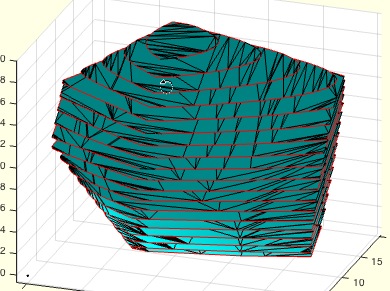
% SGslicer(SG,z) - returns the delaunayTriangulation of the sliced plane % (by Tim Lueth, VLFL-Lib, 2015-JAN-07 as class: SLICES) % % Efficient, modern and powerful version of VLELslicer/VLELslicer2 that % uses delaunayTriangulation for reconstruction and calulation of upper % and lower cutted facets in addition. % Without output parameters, the result is shown in VLFLfigure % Modified in June 2015 to support already cutted objects (lines in the % cutting plane). There is still no possibility to cut parts at the outer % boundaries (surfaces) of the object. (Status of: 2015-06-21) % % [TR2,EL,SIL,FIL,FLO,FLU,warn]=SGslicer(SG,z) % === INPUT PARAMETERS === % SG: Solid Geometry (VL,FL) % z: z value for slicing % === OUTPUT RESULTS ====== % TR2: Delaunay Triangulation of the cutting plane % EL: Border Edge List of TR2 (TR2.Constraints) % SIL: Surface Index List (Index of separated surface areas) % FIL: Facet index list of the cutted facets -1=below, +1= up, 0=cutted % FLO: Facet list upper related to [SG.VL; TR2.Points] % FLU: Facet list lower related to [SG.VL; TR2.Points] % warn: % % EXAMPLE: SGslicer (SGsample(7),+10); % |
exp_2015_01_07b- EXPERIMENT SCRIPT for testing SGslicer |
 |
% exp_2015_01_07b - EXPERIMENT SCRIPT for testing SGslicer % (by Tim Lueth, VLFL-Lib, 2015-JAN-07 as class: EXPERIMENTS) % % exp_2015_01_07b % |
PLELhsort(PL,EL,SIL)- returns a hierarchy index list for a PL,EL,SIL |
 |
% PLELhsort(PL,EL,SIL) - returns a hierarchy index list for a PL,EL,SIL % (by Tim Lueth, VLFL-Lib, 2015-JAN-05 as class: SLICES) % % PL,EL, and SIL are unchanged. The hierarchy index list contains the % index of the enclosing contour % With PLELhsort it is possible to find the outside contours of a slice % (0), which is sometimes better than a freeBoundary % (Status of: 2015-01-05) % % HIL=PLELhsort(PL,EL,SIL) % === INPUT PARAMETERS === % PL: Point List % EL: Edge List % SIL: Surface Index List % === OUTPUT RESULTS ====== % HIL: hierarchy index list % |
exp_2015_01_05 (n,dz)- EXPERIMENT for hierarchical ordering of VLEL |
 |
% exp_2015_01_05 (n,dz) - EXPERIMENT for hierarchical ordering of VLEL % (by Tim Lueth, VLFL-Lib, 2015-JAN-05 as class: EXPERIMENTS) % % Testing procedure for SGslicer and ELofFLborder2 and PLELhsort % 1. Slicing using SGslicer % 2. Connect the border edges of the Triagulation using ELofFLborder2 % 3. Calculate the Hierarchy index % 4. Use only the outer contours (Status of: 2015-01-05) % % exp_2015_01_05([n,dz]) % === INPUT PARAMETERS === % n: SGsample(positive); CPLsample(negative) or SG % dz: slicing step (positive) slice value (negative) % |
colofn(i,colbar,colstr)- returns a color char for a number 0..7 |
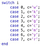 |
% colofn(i,colbar,colstr) - returns a color char for a number 0..7 % (by Tim Lueth, VLFL-Lib, 2015-JAN-05 as class: AUXILIARY PROCEDURES) % % simple auxiliary fnctn for color use in for loops (Status of: % 2017-06-17) % % See also: nofcolmap, color, VLcol % % c=colofn(i,[colbar,colstr]) % === INPUT PARAMETERS === % i: integer number % colbar: order of colors; default is 'kbgcmyrw' % colstr: colorstring such as 'R*--' % === OUTPUT RESULTS ====== % c: color char string % |
ELofFLborder2(FL)- returns the border edges of a surface |
 |
% ELofFLborder2(FL) - returns the border edges of a surface % (by Tim Lueth, VLFL-Lib, 2015-JAN-05 as class: SLICES) % % First the surface is separated into areas that have no common edges % (ELorder). Then for each area, the edges with only one direction are % the border edges. % Should replace ELofFLborder one day. (Status of: 2015-01-05) % % [EL,SIL]=ELofFLborder2(FL) % === INPUT PARAMETERS === % FL: Facet list % === OUTPUT RESULTS ====== % EL: Edge list % SIL: Surface index list % |
exp_2015_01_04b (SG,dz)- EXPERIMENT that shows the use of SGslicer and freeboundary |
 |
% exp_2015_01_04b (SG,dz) - EXPERIMENT that shows the use of SGslicer and % freeboundary % (by Tim Lueth, VLFL-Lib, 2015-JAN-04 as class: EXPERIMENTS) % % Towards a reimplementation of VLFLclosure - here we see the sliced % freeboundary % If the procedure is interrupted by Ctrl-C you see the inner part of the % sliced solid (Status of: 2015-01-04) % % exp_2015_01_04b(SG,[dz]) % === INPUT PARAMETERS === % SG: Solid Geometry (VL,FL) % dz: slicing distance % |
exp_2015_01_04 (SG,dz)- EXPERIMENT that shows the use of SGslicer and freeboundary |
 |
% exp_2015_01_04 (SG,dz) - EXPERIMENT that shows the use of SGslicer and % freeboundary % (by Tim Lueth, VLFL-Lib, 2015-JAN-04 as class: EXPERIMENTS) % % Towards a reimplementation of VLFLclosure % If the procedure is interrupted by Ctrl-C you see the inner part of the % sliced solid (Status of: 2015-01-04) % % exp_2015_01_04(SG,[dz]) % === INPUT PARAMETERS === % SG: Solid Geometry (VL,FL) % dz: slicing distance % |
SGslicer(SG,z)- returns the delaunayTriangulation of the sliced plane |
 |
% SGslicer(SG,z) - returns the delaunayTriangulation of the sliced plane % (by Tim Lueth, VLFL-Lib, 2015-JAN-04 as class: SLICES) % % More modern version of VLELslicer/VLELslicer2 that uses % delaunayTriangulation for reconstruction. % Without an output parameter, the result is shown y VLFLfigure (Status % of: 2015-01-04) % % [TR2,EL,SIL]=SGslicer(SG,z) % === INPUT PARAMETERS === % SG: Solid Geometry (VL,FL) % z: z value for slicing % === OUTPUT RESULTS ====== % TR2: Crossing vertex list of the selected slice % EL: Crossing line list of the selected slice % SIL: Normal vector list of the crossing lines % % EXAMPLE: Generate a simple octagon (5x5x20) % [VL,FL]=VLFLcylinder(20,5/cos(pi/8),8-1,1); % [CVL,CLL,NL]=VLELslicer (VL,FL,0) % VLELplot (CVL,CLL,'r*-',NL); % |
SGseparate(SG,i)- plots or returns sorted surfaces or one surface of a solid geometry |
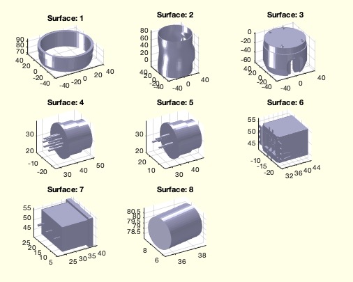 |
% SGseparate(SG,i) - plots or returns sorted surfaces or one surface of a solid geometry % (by Tim Lueth, VLFL-Lib, 2015-JAN-04 as class: SURFACES) % % SGseparate is a newer (faster and more convinient) version of % VLFLseparate % Based on ELorder and VLELselect. % With only one surface is asked, surface is moved into 1st. Quadrant % With no output parmeter, the surface(s) are plotted using VLFLfigure % With no SG specified, VLFLui is used to read in an STL-File % 2017-06-14: i can be index or index list (Status of: 2017-07-11) % % Introduced first in SolidGeometry 2.1 % % See also: SGsurfaces, SGanalyzeGroupParts, SGanalyzePenetration, % VLFLseparate, SGorder, TRorder % % [SG,SIL,n,BBi]=SGseparate([SG,i]) % === INPUT PARAMETERS === % SG: Solid Geometry; if empty % i: index list of single/selected surface % === OUTPUT RESULTS ====== % SG: Solid Geoemtry % SIL: Surface Index List % n: number of closed surfaces % BBi: Cell list of Bounding Boxes of the Solids % % EXAMPLE: % SGseparate(J1,[1,2,4]) % % See also: SGsurfaces, SGanalyzeGroupParts, SGanalyzePenetration, % VLFLseparate, SGorder, TRorder % % % Copyright 2015-2018 Tim C. Lueth |
exp_2015_01_03b(n,a)- Experiment to improve TRofSG |
 |
% exp_2015_01_03b(n,a) - Experiment to improve TRofSG % (by Tim Lueth, VLFL-Lib, 2015-JAN-03 as class: EXPERIMENTS) % % [ELFL,SIL,nv]=exp_2015_01_03b([n,a]) % === INPUT PARAMETERS === % n: n in sGsample(positive) or CPLsample (negative) % a: index or normal vector % === OUTPUT RESULTS ====== % ELFL: % SIL: % nv: % |
exp_2015_01_03(n)- EXPERIMENT to remove the bug from PLELofFeatureEdges2 in FLfeatureEdgeSurface |
 |
% exp_2015_01_03(n) - EXPERIMENT to remove the bug from % PLELofFeatureEdges2 % (by Tim Lueth, VLFL-Lib, 2015-JAN-03 as class: EXPERIMENTS) % % The BUG existing in Matlab is that % faceNormal NNED TO BE ROUNDED WITH 1e-6. % Afterwards the procedure works well. (Status of: 2015-01-03) % % ELFL=exp_2015_01_03([n]) % === INPUT PARAMETERS === % n: % === OUTPUT RESULTS ====== % ELFL: % |
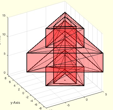
TR3ofSG(SG)- returns the triangulation for a solid gemeotry |
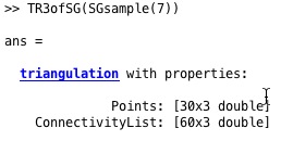 |
% TR3ofSG(SG) - returns the triangulation for a solid gemeotry % (by Tim Lueth, VLFL-Lib, 2015-JAN-03 as class: SURFACES) % % single line macro: simple auxiliary procedure (Status of: 2015-01-03) % % TR=TR3ofSG(SG) % === INPUT PARAMETERS === % SG: SG.VL, SG.FL % === OUTPUT RESULTS ====== % TR: Triangulation nx3 % |
FEplot(A,)- plots the featureEdges of TR, SG or VLFL |
 |
% FEplot(A,) - plots the featureEdges of TR, SG or VLFL % (by Tim Lueth, VLFL-Lib, 2015-JAN-03 as class: VISUALIZATION) % % FEplot(SG) % FEplot(VL,FL) % default angle is 1e-3 (Status of: 2017-04-05) % % Introduced first in SolidGeometry 2.1 % % See also: FSplot, FLfeatureEdgeSurface2, PLELofFeatureEdges, % PLELofFeatureEdges2, TRfeatureEdgeFacets, FLfeatureEdgeSurface % % FEplot(A,[]) % === INPUT PARAMETERS === % A: surface (Tetrahedron, Triangulation, Solid) % % EXAMPLE: FEplot(SGsample(3)) % % See also: FSplot, FLfeatureEdgeSurface2, PLELofFeatureEdges, % PLELofFeatureEdges2, TRfeatureEdgeFacets, FLfeatureEdgeSurface % % % Copyright 2015-2017 Tim C. Lueth |
PLradialEdges(PL,R,cvk,wmin,wmax,KL,m)- returns a point list (PL) with rounded edges |
 |
% PLradialEdges(PL,R,cvk,wmin,wmax,KL,m) - returns a point list (PL) with rounded edges % (by Tim Lueth, VLFL-Lib, 2015-JAN-02 as class: ANALYZING PROCEDURES) % % PLradialEdges IS INDEPENDENT AND NOT USING PLtangentcirc! % % Replaces all/convex/concave edges with an angle in a defined intervall % [0,180] by a radial curve. The number of curve points can be specified % too (default is nofrd). The fnctns accepts a single CPL (without NaN) % or PL and returns always a PL! (Status of: 2018-07-28) % % Introduced first in SolidGeometry 2.1 % % See also: VLradialEdges, VLtangentcirc, PLtangentcirc % % NPL=PLradialEdges(PL,[R,cvk,wmin,wmax,KL,m]) % === INPUT PARAMETERS === % PL: Point list nx2 % R: Radius; default is 1 % cvk: 0==all; +1=concave, -1=convex % wmin: minimal abs angle to handle; default is 0 % wmax: maximum abs angle to handle; default is pi % KL: nr of sections of a line; 2 are required for radius at 90degree; % % m: number of points; default is nofrd % === OUTPUT RESULTS ====== % NPL: New point list % % EXAMPLE: VLFLfigure; % C=CPLsample(1); % CPLplot(C,'m'); CPLplot(PLradialEdges(C,1)); % PLradialEdges(PLstar(50,10),5); % % See also: VLradialEdges, VLtangentcirc, PLtangentcirc % % % Copyright 2015-2018 Tim C. Lueth |
PLangle(PL)- returns the angles of a points list |
 |
% PLangle(PL) - returns the angles of a points list % (by Tim Lueth, VLFL-Lib, 2015-JAN-02 as class: ANALYZING PROCEDURES) % % In contrast to VLangle, PLangle uses crossz to calculate an % orientation: Positive values are mathematical positive (right hand). % (Status of: 2017-08-12) % % Introduced first in SolidGeometry 2.1 % % See also: VLangle, diffangle, PLangle2 % % [w,d]=PLangle(PL) % === INPUT PARAMETERS === % PL: vector list % === OUTPUT RESULTS ====== % w: angle list % d: distance list % % EXAMPLE: % [PLstar(10,10) PLangle(PLstar(10,10))/pi*180] % % See also: VLangle, diffangle, PLangle2 % % % Copyright 2015-2017 Tim C. Lueth |
exp_2015_01_02 (nr)- EXPERIMENT to show the use of FLfeatureEdgeSurface |
 |
% exp_2015_01_02 (nr) - EXPERIMENT to show the use of FLfeatureEdgeSurface % (by Tim Lueth, VLFL-Lib, 2015-JAN-02 as class: EXPERIMENTS) % % Simple experiment to test the procedure FLfeatureEdgeSurface, similar % to 2014_12_31 (Status of: 2015-01-02) % % exp_2015_01_02([nr]) % === INPUT PARAMETERS === % nr: Nr of SGsample (positive value) or CPLsample (negative value) % % EXAMPLE: exp_2015_01_02 (-7) % |
TRofSGxor(SG,TR4)- removes tetrahedrons to create features edges which are existing in a surface |
 |
% TRofSGxor(SG,TR4) - removes tetrahedrons to create features edges which % are existing in a surface % (by Tim Lueth, VLFL-Lib, 2015-JAN-02 as class: TETRAHEDRONS) % % This procedure calculates the freeBoundary of the points of a surface % model and compares the featureEdges of the freeBoundary with the % original featureEdges of a solid. All tetrahedrons are removed linked % to featureEdges that exist in the original surface but not in the % tetrahedron model. % An optional input argument is a preprocessed tetrahedron triangulation. % This procedure is used by TRofSG. In combination with TRofSGdiff % (removement of outside tetrahedons), TRofSGxor (removement of outside % tetrahedons) will create a tetrahedron triangulation for one single % surface triangulation. This procedure works for only ONE closed surface. % (Status of: 2015-01-02) % % TR4=TRofSGxor(SG,[TR4]) % === INPUT PARAMETERS === % SG: Solid geometry (SG.VL,SG>FL) % TR4: tetrahedron triangulation % === OUTPUT RESULTS ====== % TR4: tetrahedron triangulation volume model % |
TRofSGdiff(SG,TR4)- removes tetrahedrons that have features edges which are not existing in a surface |
 |
% TRofSGdiff(SG,TR4) - removes tetrahedrons that have features edges % which are not existing in a surface % (by Tim Lueth, VLFL-Lib, 2015-JAN-02 as class: TETRAHEDRONS) % % This procedure calculates the freeBoundary of the points of a surface % model and compares the featureEdges of the freeBoundary with the % original featureEdges of a solid. All tetrahedrons are removed that % create featureEdges that are not existing in the original surface. % An optional input argument is a preprocessed tetrahedron triangulation. % This procedure is used by TRofSG. In combination with TRofSGxor % (removement of outside tetrahedons), TRofSGdiff (removement of outside % tetrahedons) will create a tetrahedron triangulation for one single % surface triangulation. This procedure works for only ONE closed surface. % (Status of: 2015-01-02) % % TR4=TRofSGdiff(SG,[TR4]) % === INPUT PARAMETERS === % SG: Solid geometry (SG.VL,SG>FL) % TR4: tetrahedron triangulation % === OUTPUT RESULTS ====== % TR4: tetrahedron triangulation volume model % |
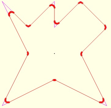
PLstar(R,nf,dw,Ry,ow,sk)- returns a 2D point list of a star or star segment |
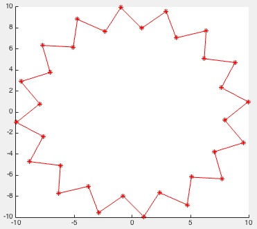 |
% PLstar(R,nf,dw,Ry,ow,sk) - returns a 2D point list of a star or star segment % (by Tim Lueth, VLFL-Lib, 2015-JAN-01 as class: AUXILIARY PROCEDURES) % % PLstar starts not(!) at (R,0), but the first edge is going in % y-direction. This has been done to simply generate squares or % 2*n-Polygons. By using the offset angle, it is possible to start where % you want. (Status of: 2017-01-05) % % See also: PLcircle, PLcircseg, PLevolvente, PLgear, PLhelix, PLkidney, % PLrand, PLspiral, PLsquare % % PL=PLstar(R,[nf,dw,Ry,ow,sk]) % === INPUT PARAMETERS === % R: Radius % nf: number of facets (default is nofrd (R,0.05)) % dw: circle segment ](0..2(pi] (default is 2*pi) % Ry: Radius if ellipse (default is R) % ow: Offset angle % sk: shortage factor;default 0.0 % === OUTPUT RESULTS ====== % PL: Point / Vertex list % |
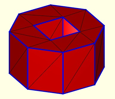
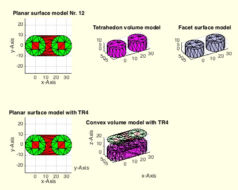
TRofSG(SG)- Creates a tetrahedron model from a surface model based on feature edges |
 |
% TRofSG(SG) - Creates a tetrahedron model from a surface model based on % feature edges % (by Tim Lueth, VLFL-Lib, 2014-DEZ-31 as class: TETRAHEDRONS) % % extracted from exp_2014-12-30d. Feature edges that exist in the % freeBoundary of a delaunayTriangulation, created from the points of a % surface model, but exist not in the surface model, can be removed % recursively by removing the attached tetrahedrons. % WORK in progress % Use FEplot or exp_2014_12_30e to understand the reason for failing % (Status of: 2015-01-02) % % TR=TRofSG(SG) % === INPUT PARAMETERS === % SG: Solid Surface Model % === OUTPUT RESULTS ====== % TR: Solid Tetrahedron Model % % EXAMPLE: Create two tetrahedron volume models from two surfaces % VLFLfigure; view(-30,30); % TR=TRofSG(SGofCPLz(CPLsample(12),10)); TRplot(TR) % |
FLfeatureEdgeSurface(TR3,angle)- returns a surface facet list based on a given surface triangulation |
 |
% FLfeatureEdgeSurface(TR3,angle) - returns a surface facet list based on a given surface triangulation % (by Tim Lueth, VLFL-Lib, 2014-DEZ-30 as class: SURFACES) % % This fnctn analyses the feature edges of a surface, reconnects them % into contours, and uses delaunay triangulation on the same points to % recalculate the surface. It uses % TRfeatureEdgeFacets % PLELofFeatureEdges2 % FLofVLELn % for reconstruction. (Status of: 2017-04-05) % % See also: FLfeatureEdgeSurface, FLfeatureEdgeSurface2, % PLELofFeatureEdges, PLELofFeatureEdges2, TRfeatureEdgeFacets, FEplot % % FL=FLfeatureEdgeSurface(TR3,angle) % === INPUT PARAMETERS === % TR3: Surface volume triangulation % angle: filter angle for feature edges % === OUTPUT RESULTS ====== % FL: Facet List w.r.t TR3.Points % % EXAMPLE: Create a solid and recreate the surface % SG=SGsample(7); % VLFLplots(SG.VL, % FLfeatureEdgeSurface(triangulation(SG.FL,SG.VL),0.01),'g'); % % |
FLofVLELn(VL,EL,nv)- returns the facet list for a vertex list and a planar edge list in 3D |
 |
% FLofVLELn(VL,EL,nv) - returns the facet list for a vertex list and a % planar edge list in 3D % (by Tim Lueth, VLFL-Lib, 2014-DEZ-30 as class: AUXILIARY PROCEDURES) % % Similiar to FLofVLEL, using delaunayTri, bit in addition the contour is % decomposed in facet with same normal vectors. The result is much better % than FLofVLEL/Delaunaytri, if enough vertices are used. % Use FLofVLEL2 (VL,EL) for optimal results % Use FLofVLEL (VL,EL) for delaunay results % Use FLofVL for quick and dirty results % It is used in combination with feature edges. % (Status of: 2012-11-17) % % FL=FLofVLELn(VL,EL,nv) % === INPUT PARAMETERS === % VL: Vertex list % EL: Edge list % nv: normal vector, has to be correct % === OUTPUT RESULTS ====== % FL: Facet list % |
PLELofFeatureEdges2(TR,alpha)- returns sorted closed polygon edge lists of the feature edges of a solid |
 |
% PLELofFeatureEdges2(TR,alpha) - returns sorted closed polygon edge lists of the feature edges of a solid % (by Tim Lueth, VLFL-Lib, 2014-DEZ-30 as class: SURFACES) % % fast and powerful fnctn that links the feature edges to closed polygon % edge lists with a defined normal vector % Uses: TRfeatureEdgeFacets % In contrast to PLELofFeatureEdges2, an additional column is added that % identifies the planes (Status of: 2017-04-05) % % See also: FLfeatureEdgeSurface, FLfeatureEdgeSurface2, % PLELofFeatureEdges, TRfeatureEdgeFacets, FEplot % % [ELFL,SIL]=PLELofFeatureEdges2(TR,[alpha]) % === INPUT PARAMETERS === % TR: surface triangulation for feature edges % alpha: feature edge angle % === OUTPUT RESULTS ====== % ELFL: % SIL: Selected Index List for % % EXAMPLE: Recreate the polygons of a % closeall; SG=SGsample(16); % TR=triangulation(SG.FL,SG.VL); % VLFLfigure; [ELFL,SIL]=PLELofFeatureEdges (TR); % |
exp_2014_12_31 (nr)- EXPERIMENT to reconstruct the surface |
 |
% exp_2014_12_31 (nr) - EXPERIMENT to reconstruct the surface % (by Tim Lueth, VLFL-Lib, 2014-DEZ-30 as class: EXPERIMENTS) % % exp_2014_12_31([nr]) % === INPUT PARAMETERS === % nr: SGsample number or CPLsample number % |
exp_2014_12_30- EXPERIMENT to develop the function TRofSG |
 |
% exp_2014_12_30 - EXPERIMENT to develop the fnctn TRofSG % (by Tim Lueth, VLFL-Lib, 2014-DEZ-30 as class: EXPERIMENTS) % % There exist several experiments of this day % exp_2014_12_30: showing the freeBoundary of delaunayTriangulation % exp_2014_12_30b: showing the additional featureEdges % exp_2014_12_30c: development of TRofSGdiff % exp_2014_12_30d: core part of TRofSGdiff % exp_2014_12_30e: showing the method of TRofSGxor % exp_2014_12_30f: show the final use of TRofSG % (Status of: 2015-01-02) % % exp_2014_12_30 % % EXAMPLE: Testing TRofSG; % exp_2014_12_30f(7) % |
exp_2014_12_29(nr)- |
 |
% exp_2014_12_29(nr) - % (by Tim Lueth, VLFL-Lib, 2014-DEZ-29 as class: EXPERIMENTS) % % NL=exp_2014_12_29([nr]) % === INPUT PARAMETERS === % nr: % === OUTPUT RESULTS ====== % NL: % |
exp_2014_12_26b(n)- EXPERIMENT extruding different CPL analyzing inside & outside points |
 |
% exp_2014_12_26b(n) - EXPERIMENT extruding different CPL analyzing % inside & outside points % (by Tim Lueth, VLFL-Lib, 2014-DEZ-26 as class: EXPERIMENTS) % % procedure 2014_12_26 generates CPLs using CPLsample. % In comparison to 2014_12_26, this procedure also analyzes the % individual contours of the inside facets to compare the use of % tetrahedrons that consists only of points of inside or only of points % of outside. In SGsample(9) we see that the surface points of inner % surfaces are also used for outside surfaces. So, it is not unique to % extract tetrahedrons just from the points list % THE STILL EXISTING PROBLEM CAN BE SEEN WITH CPLsample(8) AND % CPLsample(9): (Status of: 2014-12-27) % % fa=exp_2014_12_26b([n]) % === INPUT PARAMETERS === % n: n for CPLsample % === OUTPUT RESULTS ====== % fa: % |
exp_2014_12_26 (n)- EXPERIMENT extruding different CPL analyzing outside points |
 |
% exp_2014_12_26 (n) - EXPERIMENT extruding different CPL analyzing % outside points % (by Tim Lueth, VLFL-Lib, 2014-DEZ-26 as class: EXPERIMENTS) % % procedure 2014_12_26 generates CPLs using CPLsample. % In comparison to 2014_12_26b, this procedure analyzes the individual % contours of the inside facets to compare the use of tetrahedrons that % consists only of points of outside. In SGsample(9) we see that the % surface points of inner surfaces are also used for outside surfaces. % So, it is not unique to extract tetrahedrons just from the points list % THE STILL EXISTING PROBLEM CAN BE SEEN WITH CPLsample(8) AND % CPLsample(9): (Status of: 2014-12-26) % % exp_2014_12_26([n]) % === INPUT PARAMETERS === % n: n for CPLsample % |
CPLsample(Nr,T)- returns a a closed polygon list for different tests and experiments |
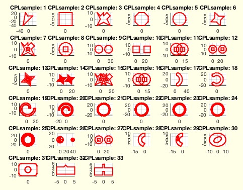 |
% CPLsample(Nr,T) - returns a a closed polygon list for different tests and experiments % (by Tim Lueth, VLFL-Lib, 2014-DEZ-26 as class: CLOSED POLYGON LISTS) % % Calling without an output parameter will always show the polygons % Calling without an input parameter will show all sample polygons % CPLsample can be called recursively to show the effect of fnctns used % on CPLsample-contours % Use CPLorder afterwards to order them. % Use CPLunite/CPLrecontour to process them. (Status of: 2018-07-28) % % Introduced first in SolidGeometry 2.1 % % See also: CPLoftext, SGsample, VLsample, PLsample, VLFLsample, % CSGsample, SGerrorsample, testfunctTL, permutevector % % [CPL,TR3]=CPLsample([Nr,T]) % === INPUT PARAMETERS === % Nr: Number of sample closed polygon list or specific CPL for display % T: Parameter for SGtrans (Value, Vector, Matrix) % === OUTPUT RESULTS ====== % CPL: Closed Polygon List % TR3: Optional delaunay triangulation of CPL using PLELofCPL % % EXAMPLE: Recontour overlapping contours % CPLsample(16) % CPLsample(CPLrecontour(CPLsample(16))) % CPLsample(CPLrecontour(flip(CPLsample(16)))) % % See also: CPLoftext, SGsample, VLsample, PLsample, VLFLsample, % CSGsample, SGerrorsample, testfunctTL, permutevector % % % Copyright 2014-2018 Tim C. Lueth |