New in SG-Lib 3.3
VLFL_Toolbox_test- publishes all tutorials to test the compliled Toolbox version |
 |
% VLFL_Toolbox_test - publishes all tutorials to test the compliled Toolbox version % (by Tim Lueth, VLFL-Lib, 2017-JAN-25 as class: FILE HANDLING) % % See also: VLFL_Toolbox_make % % VLFL_Toolbox_test % |
exp_2017_01_22- EXPERIMENT to create a arbitrary Universal Spatial Link between two frames |
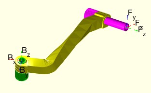 |
% exp_2017_01_22 - EXPERIMENT to create a arbitrary Universal Spatial Link between two frames % (by Tim Lueth, VLFL-Lib, 2017-JAN-22 as class: EXPERIMENTS) % % exp_2017_01_22 % |
VLFL_EXP26- Tutorial for using universal planar links |
 |
exp_2017_01_19- |
 |
% exp_2017_01_19 - % (by Tim Lueth, VLFL-Lib, 2017-JAN-19 as class: EXPERIMENTS) % % exp_2017_01_19 % |
SGTframeplot(SGN,N)- plots one ore more frame of a solid |
 |
% SGTframeplot(SGN,N) - plots one ore more frame of a solid % (by Tim Lueth, VLFL-Lib, 2017-JAN-18 as class: SURFACES) % % In contrast to SGplot, this fnctn does plot only the named frames % (Status of: 2017-01-18) % % See also: SGTget, SGTset, SGTplot, SGTremove, SGTui % % [T,a]=SGTframeplot(SGN,[N]) % === INPUT PARAMETERS === % SGN: Solid Geoemtry % N: Name of the frame to plot % === OUTPUT RESULTS ====== % T: Called Frames % a: index if Frame in Frame list % |
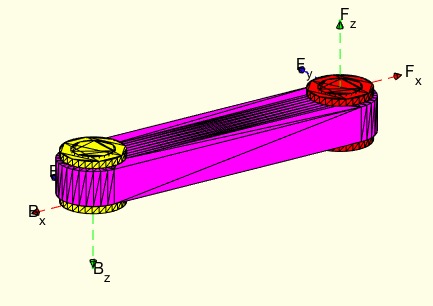
SGmodelLink2(L,L1,L2,K,H)- Creates Solid for a Link im Style "Link2" |
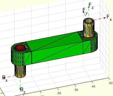 |
% SGmodelLink2(L,L1,L2,K,H) - Creates Solid for a Link im Style "Link2" % (by Tim Lueth, VLFL-Lib, 2017-JAN-18 as class: MODELING PROCEDURES) % % Notation style % 0= same level % +n = n* Height H above z plane % -n = n* height H under z plane % Knob Position % 'BU' = Base frame upper side % 'BL' = Base frame lower sider % 'FU' = Follower Frame upper side % 'FL' = Follower Frame lower sider (Status of: 2017-04-17) % % Introduced first in SolidGeometry 3.3 % % See also: SGmodelLink, SGmodelJoint, SGmodelNode, SGmodelLink3, % SGmodelKeyhole, SGmodelLink1 % % SG=SGmodelLink2([L,L1,L2,K,H]) % === INPUT PARAMETERS === % L: Length % L1: Level of Frame B; default is 0 % L2: Level of Frame F; default is 1 % K: Knob position; default is '' % H: Height of link; default is 9 % === OUTPUT RESULTS ====== % SG: Solid Geoemtry including Frames % % EXAMPLE: % A=SGmodelLink2('',0,2);SGaddrelSG(A,A,'alignT',{'B','F'}); % A=SGmodelLink2('',0,1);SGaddrelSG(A,A,'alignT',{'B','F'}); % A=SGmodelLink2('',0,-1,'BL,FU');SGaddrelSG(A,A,'alignT',{'B','F'}); % % See also: SGmodelLink, SGmodelJoint, SGmodelNode, SGmodelLink3, % SGmodelKeyhole, SGmodelLink1 % |
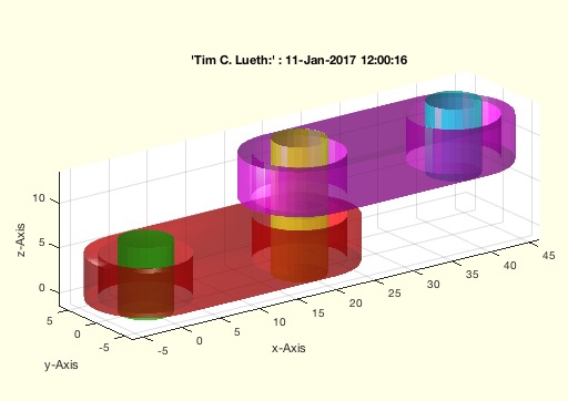
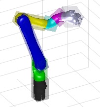
exp_2017_01_14- EXPERIMENT for printing a fourbar linkage |
 |
% exp_2017_01_14 - EXPERIMENT for printing a fourbar linkage % (by Tim Lueth, VLFL-Lib, 2017-JAN-14 as class: EXPERIMENTS) % % See also: SGmodelKeyhole, exp_2017_01_11, exp_2016_12_31, exp_2016_12_27 % % exp_2017_01_14 % |
SGwriteMultipleSTL (SG,FNAME,ONAME)- writes solid geometry in different STL files |
 |
% SGwriteMultipleSTL (SG,FNAME,ONAME) - writes solid geometry in different STL files % (by Tim Lueth, VLFL-Lib, 2017-JAN-14 as class: FILE HANDLING) % % See also: SGwriteSTL, SGwriteSeparatedSTL, SGreadSTL, % SGanalyzeGroupParts, SGarrangeSG % % SGwriteMultipleSTL(SG,[FNAME,ONAME]) % === INPUT PARAMETERS === % SG: A cell list of different solids for different file % FNAME: optional file name % ONAME: optional text name % |
depuseTLnew(fname)- return which functions in the current directory uses a named function |
 |
% depuseTLnew(fname) - return which fnctns in the current directory uses a named fnctn % (by Tim Lueth, VLFL-Lib, 2017-JAN-13 as class: AUXILIARY PROCEDURES) % % in most cases "depuseString" is much faster but cannot distinguish code % and comments and strings that are part of strings (Status of: % 2017-01-13) % % See also: depuseTL, depuseString % % a=depuseTLnew(fname) % === INPUT PARAMETERS === % fname: fnctn to search for % === OUTPUT RESULTS ====== % a: list of fnctn % |
SGbreakCorners(SG,vi,k,sf)- breaking the vertices of a solid geoemtry |
 |
% SGbreakCorners(SG,vi,k,sf) - breaking the vertices of a solid geoemtry % (by Tim Lueth, VLFL-Lib, 2017-JAN-13 as class: MODELING PROCEDURES) % % WORK in PROGRESS - NOT SATIFIYING RESULT yet (Status of: 2017-02-13) % % See also: SGbreakCorners, SGradialCorners, VLradialEdges % % SGB=SGbreakCorners(SG,[vi,k,sf]) % === INPUT PARAMETERS === % SG: Solid Geoemtry % vi: index list or vertex list of SG % k: new corner distance % sf: corner reduction factor; default is 1 [*k] % === OUTPUT RESULTS ====== % SGB: New solid with % |
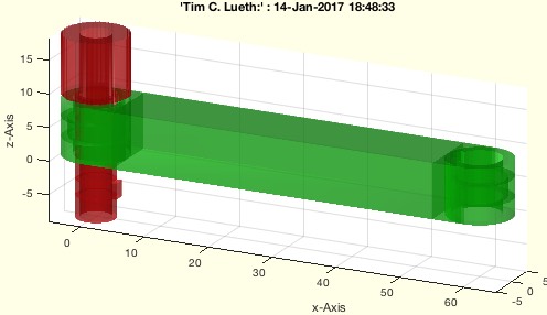
SGmodelKeyhole(RA,RO,rw,LA,LO,HO,slot)- Creates a SG including a key and a keyhole |
 |
% SGmodelKeyhole(RA,RO,rw,LA,LO,HO,slot) - Creates a SG including a key and a keyhole % (by Tim Lueth, VLFL-Lib, 2017-JAN-11 as class: MODELING PROCEDURES) % % SG modeling fnctn to create revolute joint that can be printed % assembled or separated and can be lined on an axis (Status of: % 2017-01-14) % % See also: SGmodelJoint, SGmodelLink, SGmodelNode % % [SGK,SGH,SGP,SGT,SGB]=SGmodelKeyhole([RA,RO,rw,LA,LO,HO,slot]) % === INPUT PARAMETERS === % RA: Axle Radius % RO: Outer Radius % rw: limiting turning angle; default is 2*pi % LA: [L1 L2 L3] describing key length % LO: [L1 L2 L3] describing key hole length % HO: Width of a flange in distance RO; default is 2*RO % slot: default is 0.3 mm (SLS & SLA) % === OUTPUT RESULTS ====== % SGK: Solid Geoemtry of Key % SGH: Solid Geoemtry of Keyhole % SGP: Solid Geometry of flange plate % SGT: Optional Knob on the upper side; separated from SGK % SGB: Optional Knob on the lower side; separated from SGK % % EXAMPLE: Print job was successful on Form2 SLA-Printer on 2017-01-12: % SGmodelKeyhole(3,6,'',9) % [A,B,C,D]=SGmodelKeyhole(3,6,'',9); % SGanalyzeGroupParts({A,B,C,D}) % % |
SGmodelLink3(L,lb,lf)- retuns solid geometries for R linkages |
 |
% SGmodelLink3(L,lb,lf) - retuns solid geometries for R linkages % (by Tim Lueth, VLFL-Lib, 2017-JAN-11 as class: MODELING PROCEDURES) % % See also: SGmodelLink, SGmodelLink1, SGmodelLink2 % % SGA=SGmodelLink3(L,lb,lf) % === INPUT PARAMETERS === % L: % lb: % lf: % === OUTPUT RESULTS ====== % SGA: % |
exp_2017_01_11- EXPERIMENT to create linkages using SGmodelLink2 |
 |
% exp_2017_01_11 - EXPERIMENT to create linkages using SGmodelLink2 % (by Tim Lueth, VLFL-Lib, 2017-JAN-11 as class: EXPERIMENTS) % % See also: exp_2017_01_14, SGmodelKeyhole, exp_2016_12_31, exp_2016_12_27 % % exp_2017_01_11 % |
smbSetJointInputTorque(Joint,InpPS)- smb changes a joint actuation to InputTorque |
 |
% smbSetJointInputTorque(Joint,InpPS) - smb changes a joint actuation to InputTorque % (by Tim Lueth, SimMechanics, 2017-JAN-08 as class: MODELING PROCEDURES) % % smbSetJointInputTorque(Joint,[InpPS]) % === INPUT PARAMETERS === % Joint: Unique(!) Joint name 'R1' or 'R1.J' % InpPS: % |
smbshow(block)- shows the system/subsystem diagram of the current block |
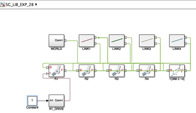 |
% smbshow(block) - shows the system/subsystem diagram of the current block % (by Tim Lueth, SimMechanics, 2017-JAN-08) % % See also: smbGetSubSystempath % % smbshow([block]) % === INPUT PARAMETERS === % block: block handle';default is gcb % |
imageFigureMovie(figh,FName)- Creates a cell list of frames to write a movie later |
 |
% imageFigureMovie(figh,FName) - Creates a cell list of frames to write a movie later % (by Tim Lueth, Video-Lib, 2017-JAN-06) % % Parameter is figure handle or: % 'start', 'record': resets the image counter % 'end'; returns the image cell list as movie % 'save'; writes the movie on disk % % To record an video start with: imageFigureMovie('record'); % To add an video image frame use: imageFigureMovie(gcf); % To save the movie use: imageFigureMovie('end','new_video.avi'); % (Status of: 2017-01-07) % % See also: imageFigureSaveMovie, imageVideoFrames, imageVideoTitle, % imageVideoTextPage, imageVideoEndtitle, imageVideoWrite, % videoCopyFrames, videoCopyCutMovies, videoWriteClipMovie % % movie=imageFigureMovie([figh,FName]) % === INPUT PARAMETERS === % figh: 'start', 'end', or gcf or figure handle % FName: Optinal filename for command 'save' % === OUTPUT RESULTS ====== % movie: [] or movie if figh=='end; % % EXAMPLE: % imageFigMovieRecord('start'); for i=1:10; imageFigMovieRecord; end; % I=imageFigMovieRecord('end') % |
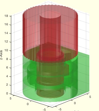
exp_2017_01_06- EXPERIMENT to create a ring |
 |
% exp_2017_01_06 - EXPERIMENT to create a ring % (by Tim Lueth, VLFL-Lib, 2017-JAN-06 as class: EXPERIMENTS) % % exp_2017_01_06 % |
BBofSG(SG,sep,kin)- returns the bounding box of a solid geoemtry |
 |
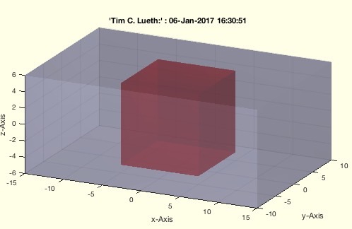
% BBofSG(SG,sep,kin) - returns the bounding box of a solid geoemtry % (by Tim Lueth, VLFL-Lib, 2017-JAN-05 as class: ANALYTICAL GEOMETRY) % % Creates the vertex list of all vertices of the solid geometry. The % calculates the bounding box. Supports nested SG. In case of kinematic % structures, only BBofSG can create turned bound boxes. (Status of: % 2017-06-14) % % See also: BBiscollofVL, BBofVL, CPLofBB, SGofBB, VLFLofBB, % outboundingbox % % [BB,SGBB]=BBofSG(SG,[sep,kin]) % === INPUT PARAMETERS === % SG: Solid Geoemtry % sep: separation of cells; default is false % kin: Frame for optimized bounding boxes; default is 'B' % === OUTPUT RESULTS ====== % BB: Bounding Box % SGBB: optional Solid Geometry of the bounding box % % EXAMPLE: % load JACO_robot % BBofSG(JACO) % BBofSG(JACO,true) % |
SGmagnifyVL(oSG,m,lim,prop)- magnifies/shrinks the dimensions of the vertex list |
 |
% SGmagnifyVL(oSG,m,lim,prop) - magnifies/shrinks the dimensions of the vertex list % (by Tim Lueth, VLFL-Lib, 2017-JAN-05 as class: ANALYTICAL GEOMETRY) % % In contrast to SGgrow, this fnctn just multiplies the vertex list with % a constant factor. The factor is either fixed or calculated from a % limiting bounding box [limx limy limz]. In the second case, the scaling % can be proportional or to fill the limiting bounding box. (Status of: % 2017-01-06) % % See also: SGgrow % % [SG,m]=SGmagnifyVL(oSG,m,[lim,prop]) % === INPUT PARAMETERS === % oSG: Original Solid Geoemtry % m: magnification value or [mx my mz] % lim: optional boundaries for magnification % prop: proportional scaling; default is true % === OUTPUT RESULTS ====== % SG: resulting Solid Geometry % m: used scaling factor [mx my mz] % % EXAMPLE: % A=SGbox([10 10 10]); % SGmagnifyVL(A,[3 2 1.5]) % |
VLFL_EXP27- |
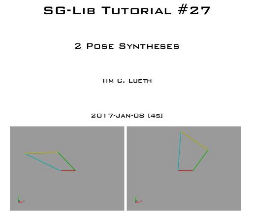 |
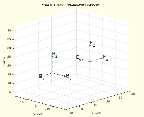
%% PUBLISHABLE VLFL_EXP27 % (by Tim Lueth, VLFL-Lib, 2017-JAN-05) %% % VLFL_EXP27 - % (by Tim Lueth, VLFL-Lib, 2017-JAN-05) % % Poses are described by the start point and end point of a link. Der % erste Punkt der Koppel legt einen Punkt fest, der zweite Punkt auch die % Richtung. Im einfachsten Fall werden 2 Posen für den Entwurf eines % Viergelenks vorgegeben. Als Lösung gibt es dann zwei geraden auf denen % jeweils der Gestellpunkt A0 oder der Gestellpunkt B0 liegen darf. Der % Kreuzungspunkt dieser beiden Geraden ist der Polpunkt P12. Im % Sonderfall liegen beide Gestellpunkt an dieser Stelle und aus dem % Viergelenk wird ein Dreieck. In jedem Fall können die Gestellpunkte so % verschoben werden, so dass auch andere Nebenbedingungen erfüllt werden % können. (Status of: 2017-01-06) % % VLFL_EXP27 % |
smbNewLineRouting (asys)- smb reroutes the lines in the existing image |
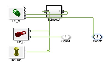 |
% smbNewLineRouting (asys) - smb reroutes the lines in the existing image % (by Tim Lueth, SimMechanics, 2017-JAN-04) % % See also: smbAddLine, smbDeleteUnconnectedLines, PLroutefind % % smbNewLineRouting([asys]) % === INPUT PARAMETERS === % asys: system; default is gcs % |
PLroutefind(PL)- returns a right angle point list between start and end point |
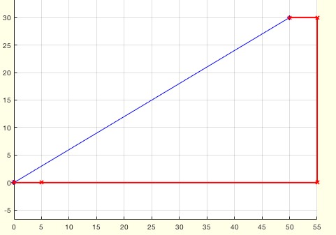 |
% PLroutefind(PL) - returns a right angle point list between start and end point % (by Tim Lueth, VLFL-Lib, 2017-JAN-04 as class: AUXILIARY PROCEDURES) % % See also: smbNewLineRouting % % NPL=PLroutefind(PL) % === INPUT PARAMETERS === % PL: Original Point List % === OUTPUT RESULTS ====== % NPL: New Point List % |