New in SG-Lib 4.1
isonVLFLedge(VL,FL,PL)- returns the triangles a vertex is on edge |
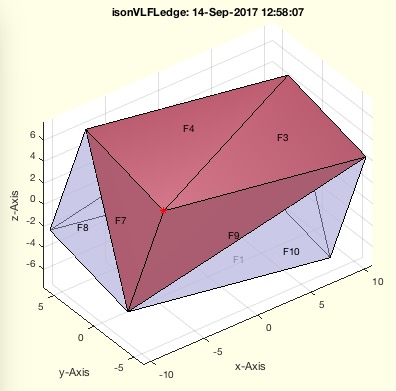 |
% isonVLFLedge(VL,FL,PL) - returns the triangles a vertex is on edge % (by Tim Lueth, VLFL-Lib, 2017-SEP-14 as class: SURFACES) % % SGintersectFacetPoints returns a vertex list of crossing points of two % surfaces. Nevertheless in case of numerical problems when a vertex is % on a a facet edge, it is not found on the corresponding negative edge % of the neighbor facet. Therefor this fnctn just makes a cross check for % all vertices and all points % NN cols; [vi fi ei ti] % vi = checked vertex index of PL % fi = facets of FL that contains PL(vi,:) % ei = edge index 1..3 of fi % ti = value between 0 and 1 end point % if ti<0 or ti>1, the point is not on the edge (Status of: 2017-09-14) % % Introduced first in SolidGeometry 4.1 % % See also: SGintersectFacetPoints, VLFLinsertFacetPoints % % NN=isonVLFLedge(VL,FL,PL) % === INPUT PARAMETERS === % VL: Vertex list of solid % FL: Face list of solid % PL: Point to check or Point List % === OUTPUT RESULTS ====== % NN: Result [n x 4] % % EXAMPLE: % SGsample(26); A=ans, isonVLFLedge(A.VL,A.FL,[0 -10 5]) % SGsample(26); A=ans, isonVLFLedge(A.VL,A.FL,[0 -10 5;10 10 -5]) % SGsample(26); A=ans, isonVLFLedge(A.VL,A.FL,[0 -10 5;20 10 -5]) % % See also: SGintersectFacetPoints, VLFLinsertFacetPoints % % % Copyright 2017 Tim C. Lueth |
barytocartUVLdelaunay(p1,p2,p3,UVL)- converts a 2d Barycentric [u,v] vertex list into a 3D Cartesian coordinate list [x, y, z] |
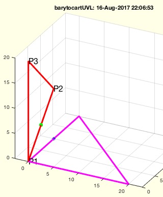 |
% barytocartUVLdelaunay(p1,p2,p3,UVL) - converts a 2d Barycentric [u,v] vertex list into a 3D Cartesian coordinate list [x, y, z] % (by Tim Lueth, VLFL-Lib, 2017-SEP-11 as class: ANALYTICAL GEOMETRY) % % Same as barytocartUVL but uses mathlabs triangulation concept % Expecting all vertices in the plane of a triangle p1p2p3, the % coordinates of the vertices can be formulated as p1 + u*(p2-p1) + v* % (p3-p1). The Barycentric coordinates are [u v]. % Both procedures can be used to solve 3D problems in 2D % % barytocartUVL is unable to detect the distance to the plane! % (Status of: 2017-09-11) % % Introduced first in SolidGeometry 4.1 % % See also: carttobaryVL, barytocartUVL, clipbarycentric % % VL=barytocartUVLdelaunay(p1,p2,p3,UVL) % === INPUT PARAMETERS === % p1: Point 1 of the triangle % p2: Point 2 of the triangle % p3: Point 3 of the triangle % UVL: Barycentric vertex list, all points in plane % === OUTPUT RESULTS ====== % VL: n x 3 list with [x y z] % % EXAMPLE: % barytocartUVLdelaunay([0 0 0],[ 0 10 10],[0 0 20],[0 0.5]) % % See also: carttobaryVL, barytocartUVL, clipbarycentric % % % Copyright 2017 Tim C. Lueth |
ELofELmesh(EL)- returns a separated EL consisting of independent meshes and a rest of points and lines |
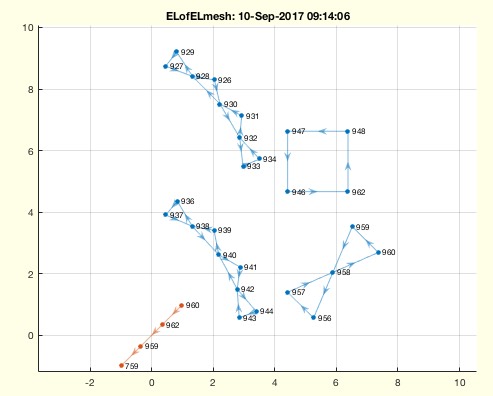 |
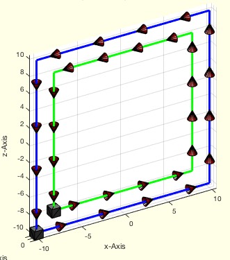
% ELofELmesh(EL) - returns a separated EL consisting of independent meshes and a rest of points and lines % (by Tim Lueth, VLFL-Lib, 2017-SEP-10 as class: EDGE LISTS) % % This fnctn will take an edge list and searches for closed meshed under % the condition of correct edge lists(!), which is not the case for % feature edges. % The results are closed meshes and a list of open lines and points % (Status of: 2018-08-28) % % Introduced first in SolidGeometry 4.1 % % See also: ELplot, graphofEL % % [NEL,CIL,ELu]=ELofELmesh(EL) % === INPUT PARAMETERS === % EL: Original edge list % === OUTPUT RESULTS ====== % NEL: New edge list (blue) % CIL: CIL of meshes % ELu: list of restpoints that are not part of a mesh (red) % % EXAMPLE: % ELofELmesh([1 2;2 3;3 1;4 1]) % ELofELmesh([1 2;2 3;1 3]) % % See also: ELplot, graphofEL % % % Copyright 2017-2018 Tim C. Lueth |
ELplot(EL)- plots the graph of the given edge list |
 |
% ELplot(EL) - plots the graph of the given edge list % (by Tim Lueth, FileMaker, 2017-SEP-09 as class: EDGE LISTS) % % This fnctn uses the digraph class and plot for drawing the edge list. % (Status of: 2018-04-18) % % Introduced first in SolidGeometry 4.1 % % See also: graphofEL % % [h,G]=ELplot(EL) % === INPUT PARAMETERS === % EL: Edge List % === OUTPUT RESULTS ====== % h: handle to plot % G: digraaph of the edge list % % EXAMPLE: % ELplot(FEofSG(SGsample(32))); % CPL=[PLcircle(5);nan nan;PLcircle(3)]; [~,EL]=PLELofCPL(CPL) % SGfigure; ELplot(EL); % X=SGsample(26); EL=ELofFL(X.FL); SGfigure; ELplot(EL,'layout','force3') % % See also: graphofEL % % % Copyright 2017-2018 Tim C. Lueth |
ELconnectedgroups(EL,vi)- returns edge lists in groups of isolate indices |
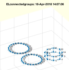 |
% ELconnectedgroups(EL,vi) - returns edge lists in groups of isolate indices % (by Tim Lueth, VLFL-Lib, 2017-SEP-08 as class: EDGE LISTS) % % Use CILofEL afterwards % Use CELofEL to create EL with same directions (Status of: 2018-08-24) % % Introduced first in SolidGeometry 4.1 % % See also: CELofEL, ELreconnect, ELofELmesh % % [NEL,CIL]=ELconnectedgroups(EL,vi) % === INPUT PARAMETERS === % EL: Edge list % vi: Optional list of interested vertices; default is '' % === OUTPUT RESULTS ====== % NEL: New Edge list; NOT SORTED ONLY GROUPED % CIL: Group Index List % % EXAMPLE: % ELconnectedgroups(FEofSG(SGsample(32))) % [NEL,CIL]=ELconnectedgroups( floor(rand(10,2)*10+1)) % % See also: CELofEL, ELreconnect, ELofELmesh % % % Copyright 2017-2018 Tim C. Lueth |
debugTL()- just prompts the current function as debug info |
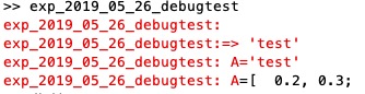 |
% debugTL() - just prompts the current fnctn as debug info % (by Tim Lueth, VLFL-Lib, 2017-SEP-06 as class: AUXILIARY PROCEDURES) % % the varargin parameter has no use but the possibility to integrate % somehow the date of the debug process somehow in the code, even it is % useful only for a human programmer (Status of: 2017-09-06) % % Introduced first in SolidGeometry 4.1 % % debugTL([]) % % EXAMPLE: debugTL('2017-09-07'); % % % Copyright 2017 Tim C. Lueth |
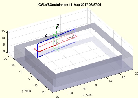
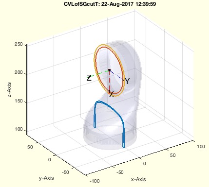
CVLofSGcutTrot(SG,T,wlim,grow)- creates contours and 2.5D solids from a rotated cross-slice of a solid. |
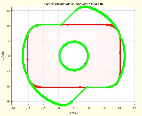 |
% CVLofSGcutTrot(SG,T,wlim,grow) - creates contours and 2.5D solids from a rotated cross-slice of a solid. % (by Tim Lueth, VLFL-Lib, 2017-SEP-05 as class: SLICES) % % uses CVLofSGT but creates the sweeped crossing area and a 2D. % This fnctn is required if an rotating solid needs volume space for the % rotation and the revolving solid has to be substracted from the % rotation partner. (Status of: 2017-09-06) % % Introduced first in SolidGeometry 4.1 % % See also: SGbool % % [CVLA,CVLB,CPLA,CPLB,A,B]=CVLofSGcutTrot(SG,[T,wlim,grow]) % === INPUT PARAMETERS === % SG: Solid Geoemtry % T: Cutting Frame; default is eye(4) % wlim: [wlim wmax]; default is [-pi/4 +pi/4]; % % grow: growing factor / slot size % === OUTPUT RESULTS ====== % CVLA: Spatial contour [n x 3] of above line % CVLB: Spatial contour [n x 3] of below line % CPLA: Planar contour [n x 2] of above line % CPLB: Planar contour [n x 2] of below line % A: Solid for contour A % B: Solid for contour B % % EXAMPLE: % CVLofSGcutTrot(SGsample(26),TofT(eye(4),0,+4),[0 pi/4]); % CVLofSGcutTrot(SGsample(27),TofT(eye(4),0,+4),[0 pi/4]); % % See also: SGbool % % % Copyright 2017 Tim C. Lueth |
SGvertexongrid(A,grid1,grid2)- returns a solid geometry with all vertices set to a grid |
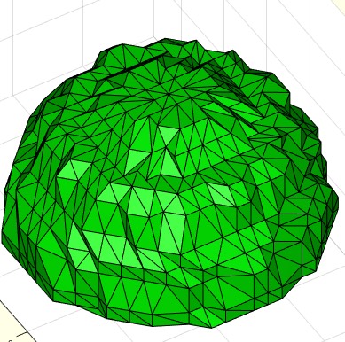 |
% SGvertexongrid(A,grid1,grid2) - returns a solid geometry with all vertices set to a grid % (by Tim Lueth, VLFL-Lib, 2017-SEP-01 as class: SURFACES) % % Three important fnctns to be used in combination with SGbool: % SGvertexongrid - maps all vertices of a solid to a grid % SGretesselate - removes small facets from a solid % SGdelaunay - retesselates alls surfaces by delaunay % (Status of: 2017-09-07) % % Introduced first in SolidGeometry 4.1 % % See also: VLFLvertexongrid, SGretesselate, SGdelaunay % % B=SGvertexongrid([A,grid1,grid2]) % === INPUT PARAMETERS === % A: Solid Geoemtry % grid1: default is 1e-3 points mapped to the same coordinates % grid2: default is 0.25*grid 1 grid the last point is mapped to % === OUTPUT RESULTS ====== % B: Final Solid % % EXAMPLE: % SG=SGsample(5), SGvertexongrid(SG,1), VLmindxyz(ans) % % See also: VLFLvertexongrid, SGretesselate, SGdelaunay % % % Copyright 2017 Tim C. Lueth |
VLFLvertexongrid(VL,FL,grid1,grid2)- returns a solid geometry with all vertices set to a grid |
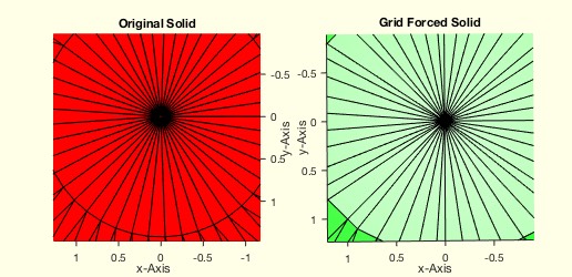 |
% VLFLvertexongrid(VL,FL,grid1,grid2) - returns a solid geometry with all vertices set to a grid % (by Tim Lueth, VLFL-Lib, 2017-SEP-01 as class: SURFACES) % % Important fnctn to be used in combination with SGbool % This fnctn uses two grids. % grid 1 is used to select all points that are conidered to have the same % coordinates % grid 2 is used to force the remaining single point to a grid position % grid 2 is an order of magnitude smaller than grid 1 (Status of: % 2017-09-01) % % Introduced first in SolidGeometry 4.1 % % See also: SGbool, VLFLremoveVertex % % [VLN,FLN]=VLFLvertexongrid([VL,FL,grid1,grid2]) % === INPUT PARAMETERS === % VL: Vertex List or Solid Geoemtry % FL: Facet List, or empty if VL=SG % grid1: default is 1e-3 % grid2: default is 0.25*grid 1 % === OUTPUT RESULTS ====== % VLN: Final Vertex List or Final Solid if nargout==1 % FLN: Final Facet List % % EXAMPLE: % A=SGsample(5), B=VLFLvertexongrid(A,'',0.1), VLmindxyz(B) % % See also: SGbool, VLFLremoveVertex % % % Copyright 2017 Tim C. Lueth |
uniquehist(A,)- performs the unique command and creates a full histogram count afterwards |
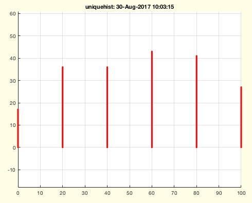 |
% uniquehist(A,) - performs the unique command and creates a full histogram count afterwards % (by Tim Lueth, VLFL-Lib, 2017-AUG-30 as class: AUXILIARY PROCEDURES) % % works exactly as unique but calculates the number of occurences % afterwards (Status of: 2017-08-30) % % Introduced first in SolidGeometry 4.1 % % See also: unique % % [C,ia,ic,h]=uniquehist(A,[]) % === INPUT PARAMETERS === % A: array A % === OUTPUT RESULTS ====== % C: unique arrary, may be sorted % ia: index vector ia % ic: index vector ib % h: number of entities of C in A % % EXAMPLE: % L=1+floor(rand(10,1)*10) % L=1+floor(rand(100,2)*10) % [a,~,~,h]=uniquehist(roundn(ELunsort(L),2),'rows'),[a h] % uniquehist(roundn(ELunsort(L),20)) % uniquehist(roundn(ELunsort(L),20),'rows') % % See also: unique % % % Copyright 2017 Tim C. Lueth |
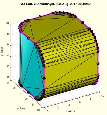
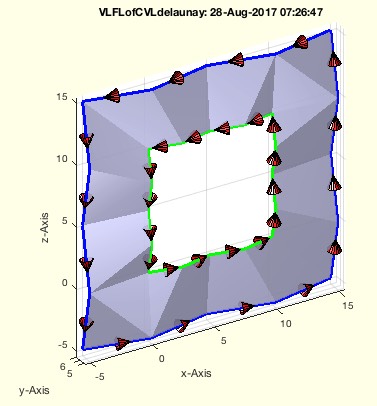
VLFLofCVLdelaunay3D(CVL)- returns the top and below tesselation for ONE closed vertex list which cuts a convex solid into two parts |
 |
% VLFLofCVLdelaunay3D(CVL) - returns the top and below tesselation for ONE closed vertex list which cuts a convex solid into two parts % (by Tim Lueth, VLFL-Lib, 2017-AUG-28 as class: SURFACES) % % In contrast to VLFLofVLELdelaunay3D, this fnctn VLFLofCVLdelaunay3D is % limited to the vertex points that are used in CVL. Based on the VL a % convex solid is created and separted into two halfs/parts by the given % EL. This works currently in 3D only for one closed contour. (Status of: % 2017-08-31) % % Introduced first in SolidGeometry 4.1 % % See also: VLedgeNormal, VLFLofCVLdelaunay2D, VLFLofVLELdelaunay3D % % [VL,FLA,FLB]=VLFLofCVLdelaunay3D([CVL]) % === INPUT PARAMETERS === % CVL: Closed Polygon Vertex List % === OUTPUT RESULTS ====== % VL: Vertex List % FLA: Facet List Above/Front of EL (CYAN) % FLB: Facet List Below/Back of EL (YELLOW) % % EXAMPLE: % VLFLofCVLdelaunay3D(VLsample(12)) % % See also: VLedgeNormal, VLFLofCVLdelaunay2D, VLFLofVLELdelaunay3D % % % Copyright 2017 Tim C. Lueth |
CVLofVLEL(VL,EL)- returns a closed polygon vertex list from a vertex list and an edge list |
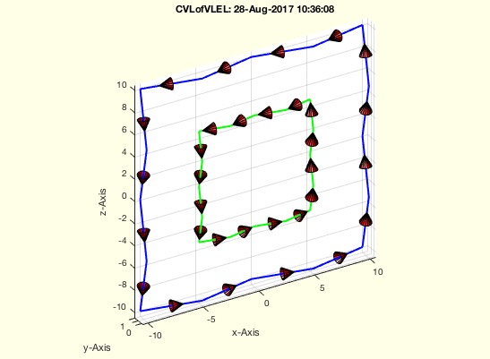 |
% CVLofVLEL(VL,EL) - returns a closed polygon vertex list from a vertex list and an edge list % (by Tim Lueth, VLFL-Lib, 2017-AUG-28 as class: CLOSED POLYGON LISTS) % % same as CPLofPLEL (Status of: 2017-08-28) % % Introduced first in SolidGeometry 4.1 % % See also: CPLofPLEL, VLELofCVL, CILofEL, CVLofVLCIL % % CVL=CVLofVLEL(VL,EL) % === INPUT PARAMETERS === % VL: Vertex List % EL: Edge list % === OUTPUT RESULTS ====== % CVL: closed polygon vertex list % % EXAMPLE: % [VL,EL]=VLELofCVL(VLsample(18)); CVLofVLEL(VL,EL) % % See also: CPLofPLEL, VLELofCVL, CILofEL, CVLofVLCIL % % % Copyright 2017 Tim C. Lueth |
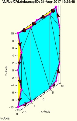
VLFLofVLELdelaunay3D(OVL,EL)- returns the top and below tesselation for ONE closed vertex list which cuts a convex solid into two parts |
 |
% VLFLofVLELdelaunay3D(OVL,EL) - returns the top and below tesselation for ONE closed vertex list which cuts a convex solid into two parts % (by Tim Lueth, VLFL-Lib, 2017-AUG-28 as class: SURFACES) % % In contrast to VLFLofCVLdelaunay3D, this fnctn VLFLofVLELdelaunay3D is % not limited to the vertex points that are used in CVL. Based on the VL % a convex solid is created and separted into two halfs/parts by the % given EL. This works currently in 3D only for one closed contour. % (Status of: 2017-08-30) % % Introduced first in SolidGeometry 4.1 % % See also: VLedgeNormal, VLFLofCVLdelaunay2D, VLFLofCVLdelaunay3D % % [VL,FLA,FLB]=VLFLofVLELdelaunay3D([OVL,EL]) % === INPUT PARAMETERS === % OVL: Original Vertex List % EL: Edge List % === PROPERTY NAMES ===== % 'nowarn' : if used; the planar warning is off % === OUTPUT RESULTS ====== % VL: Vertex List % FLA: Facet List Above/Front of EL (CYAN) % FLB: Facet List Below/Back of EL (YELLOW) % % EXAMPLE: % A=SGsample(5); EL=ELsort(FEofSG(A)); VLFLofVLELdelaunay3D(A.VL,EL); % A=SGsample(19); EL=ELsort(FEofSG(A)); VLFLofVLELdelaunay3D(A.VL,EL); % AVL=VLofCVL(VLsample(17)); AEL=ELofCVL(AVL); % VLFLofVLELdelaunay3D(AVL,AEL) % AVL=VLofCVL(VLsample(15)); AEL=ELofCVL(AVL); % VLFLofVLELdelaunay3D(AVL,AEL) % AVL=VLofCVL(VLsample(12)); AEL=ELofCVL(AVL); % VLFLofVLELdelaunay3D(AVL,AEL) % % See also: VLedgeNormal, VLFLofCVLdelaunay2D, VLFLofCVLdelaunay3D % % % Copyright 2017 Tim C. Lueth |
CVLplots(CVL,c,w,t,b,f)- similar to CVLplot but shows optionally the direction of the line segments |
 |
% CVLplots(CVL,c,w,t,b,f) - similar to CVLplot but shows optionally the direction of the line segments % (by Tim Lueth, VLFL-Lib, 2017-AUG-28 as class: VISUALIZATION) % % This procedure is different to VLELplot (Status of: 2017-08-28) % % Introduced first in SolidGeometry 4.1 % % See also: VLELplots, CPLplot, PLplot, VLplot, CVLplot % % h=CVLplots(CVL,[c,w,t,b,f]) % === INPUT PARAMETERS === % CVL: Several closed vertex list separated by nan % c: Optional color of desired edges; default changing colors % w: Optional line width; default is 1 % t: Size of a cone shaped arrow tip, default is ''=invisible % b: Size of a cube showing the start point; default is ''=invisible % f: Size of a ring showing the end point; default is ''=invisible % === OUTPUT RESULTS ====== % h: handle to drawing elements % % EXAMPLE: % SGfigure; view(-30,30); CVLplots(VLsample(18),'',3,1); % SGfigure; view(-30,30); CVLplots(VLsample(18),'',3,1,1); % SGfigure; view(-30,30); CVLplots(VLsample(18),'',3,1,1,1); % % See also: VLELplots, CPLplot, PLplot, VLplot, CVLplot % % % Copyright 2017 Tim C. Lueth |
VLELofCVL(CVL)- converts nan separated succeeding vertex lists into a vertex list and an edge list |
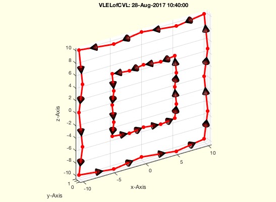 |
% VLELofCVL(CVL) - converts nan separated succeeding vertex lists into a vertex list and an edge list % (by Tim Lueth, VLFL-Lib, 2017-AUG-27 as class: AUXILIARY PROCEDURES) % % This fnctn removes the NaN from the original point list. The % orientation (cw/ccw) is not changed. It is exactly the same as % PLELofCPL (Status of: 2017-08-28) % % Introduced first in SolidGeometry 4.1 % % See also: ELofCVL, PLELofCPL, CVLofVLEL % % [VL,EL]=VLELofCVL(CVL) % === INPUT PARAMETERS === % CVL: NAN Separated Vertex List % === OUTPUT RESULTS ====== % VL: Vertex List (without NaN) % EL: Edge list % % EXAMPLE: % [VL,EL]=VLELofCVL(VLsample(19)); CVL=CVLofVLEL(VL,EL); % VLELofCVL(VLsample(19)); % % See also: ELofCVL, PLELofCPL, CVLofVLEL % % % Copyright 2017 Tim C. Lueth |
VLof2VLnonmanifold(VLA,VLB)- returns vertex list and indices of non manifold vertices on TWO DIFFERENT vertex lists |
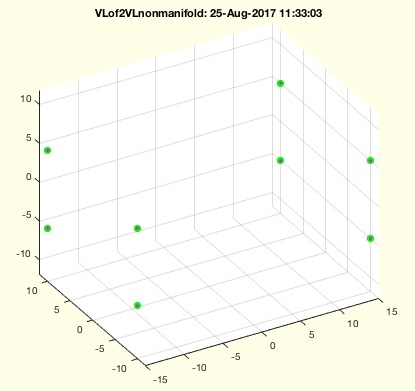 |
% VLof2VLnonmanifold(VLA,VLB) - returns vertex list and indices of non manifold vertices on TWO DIFFERENT vertex lists % (by Tim Lueth, VLFL-Lib, 2017-AUG-25 as class: SURFACES) % % This fnctn is able to detect potential problems in SGbool before % execution (Status of: 2017-08-25) % % Introduced first in SolidGeometry 4.1 % % See also: VLmindxyz, VLofcorruptedFL % % [NML,nma,nmb]=VLof2VLnonmanifold(VLA,VLB) % === INPUT PARAMETERS === % VLA: Vertex list A % VLB: Vertex list B % === OUTPUT RESULTS ====== % NML: Non manifold vertices; identical points used in both solids % nma: % nmb: % % EXAMPLE: % [A,B]=CSGsample(12); % VLof2VLnonmanifold(roundn(A.VL,1e-4),roundn(B.VL,1e-4)) % % See also: VLmindxyz, VLofcorruptedFL % % % Copyright 2017 Tim C. Lueth |
FLofELinFL(FL,EL,)- finds one ore more edges in a facets list |
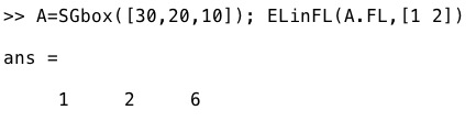 |
% FLofELinFL(FL,EL,) - finds one ore more edges in a facets list % (by Tim Lueth, VLFL-Lib, 2017-AUG-24 as class: AUXILIARY PROCEDURES) % % this is a search fnctn ismember(FL,EL) (Status of: 2017-08-25) % % Introduced first in SolidGeometry 4.1 % % See also: FLunique, ELinFL, ELofFL, ELofFLborder % % [FL,ci]=FLofELinFL(FL,EL,[]) % === INPUT PARAMETERS === % FL: Facet list % EL: Edge List % === OUTPUT RESULTS ====== % FL: Faces that contain the edges % ci: selection index % % EXAMPLE: % A=SGbox([30,20,10]); ELinFL(A.FL,[1 2]) % % See also: FLunique, ELinFL, ELofFL, ELofFLborder % % % Copyright 2017 Tim C. Lueth |
VLmindxyz(VL,Name,FL,grid)- returns the minimal distance larger than zero |
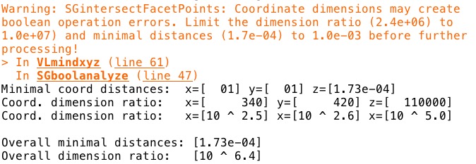 |
% VLmindxyz(VL,Name,FL,grid) - returns the minimal distance larger than zero % (by Tim Lueth, VLFL-Lib, 2017-AUG-24 as class: ANALYTICAL GEOMETRY) % % The smallest number in matlab different from zero is eps ~1e-15; % The typical arithmetic error of ordinary calculation is ~1e-12; % The smallest trigonometric number bigger than zero is eps2 ~1e-07; % A boolean surface operation should use coordinate grids ~1e-03; % The crossing points NPL of those coordinate would be up to ~1e-12; % Rounding limits > 1e-12 will create new point in triangulation; % (Status of: 2017-08-24) % % Introduced first in SolidGeometry 4.1 % % See also: VLmindist, eps, eps2, epsdyn, SGboolanalyze % % [dmin,dmm]=VLmindxyz(VL,[Name,FL,grid]) % === INPUT PARAMETERS === % VL: vector list % Name: Optional Name string for warnings and verbose print % FL: Optional Facet list to get information on Area and collapsed facets % grid: Optional Grid size to estimate the problems by grid rounding % === OUTPUT RESULTS ====== % dmin: absolute minimal distance % dmm: abolute maximum dimension % % EXAMPLE: % VLmindxyz(SGsample(5)), % Shows the minimal point distance for a half % sphere % % See also: VLmindist, eps, eps2, epsdyn, SGboolanalyze % % % Copyright 2017 Tim C. Lueth |
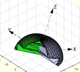
SGdelaunay(A,alpha)- returns a solid with delaunay surfaces |
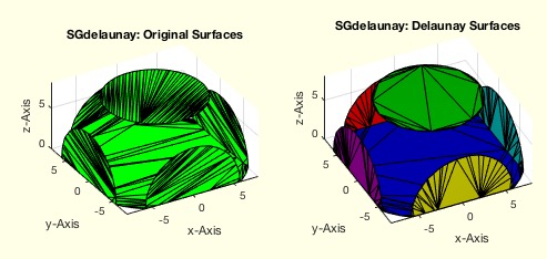 |
% SGdelaunay(A,alpha) - returns a solid with delaunay surfaces % (by Tim Lueth, VLFL-Lib, 2017-AUG-24 as class: SURFACES) % % This fnctn takes all planar surfaces and creates a new delaunay % tesselation for this planar surfaces % ATTENTION. The new facet list will not change in size! % ATTENTION. Sometimes the new surface is only mirrored on turned % ATTENTION. The alpha value will smoothen the surface but can lead to % undesired side effects % A larger alpha value will flatten spherical surfaces and create % undesired spherical shortcuts! (Status of: 2017-08-24) % % Introduced first in SolidGeometry 4.1 % % See also: SGreduceVLFL, SGretesselate % % SGN=SGdelaunay(A,[alpha]) % === INPUT PARAMETERS === % A: Original Solid Geometry % alpha: feature surface angle; default is 0.01 % === OUTPUT RESULTS ====== % SGN: Solid Geometry with delaunay surfaces % % EXAMPLE: % A=SGsample(5); B=SGcutBB(A,BBofSG(A)*0.8,0.1,'bool'); % SGdelaunay(B,0.01) % % See also: SGreduceVLFL, SGretesselate % % % Copyright 2017 Tim C. Lueth |
SGtransrelT(SG,T0,T)- tranforms a solid relative to known one |
 |
% SGtransrelT(SG,T0,T) - tranforms a solid relative to known one % (by Tim Lueth, VLFL-Lib, 2017-AUG-22 as class: SURFACES) % % % SGN=SGtransT(SG,T0*T*(eye(4)/T0)); % (Status of: 2017-08-23) % % Introduced first in SolidGeometry 4.1 % % See also: SGtrans, SGtrans0, SGtrans1, SGtransP, SGtransR, % SGtransrelSG, SGtransT % % SGN=SGtransrelT(SG,T0,T) % === INPUT PARAMETERS === % SG: Solid Geometry % T0: Reference Frame Matrix or string for SGTget % T: Relative Transformation Frame % === OUTPUT RESULTS ====== % SGN: Spatial transformed solid % % See also: SGtrans, SGtrans0, SGtrans1, SGtransP, SGtransR, % SGtransrelSG, SGtransT % % % Copyright 2017 Tim C. Lueth |
CVLclipT(CVL,T,ax)- returns a clipped CVL relative to a HT matrix |
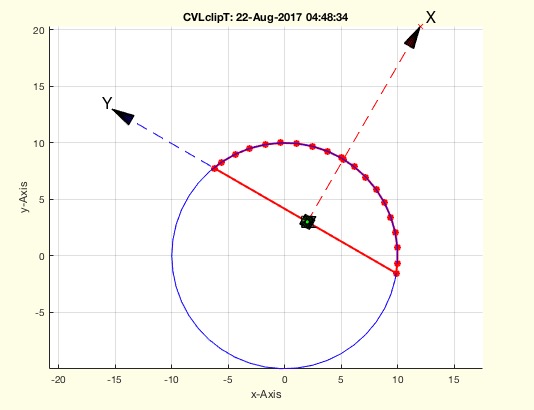 |
% CVLclipT(CVL,T,ax) - returns a clipped CVL relative to a HT matrix % (by Tim Lueth, VLFL-Lib, 2017-AUG-22 as class: ANALYTICAL GEOMETRY) % % Be careful if more than one axis is clipped! unexpected results ..... % (Status of: 2017-08-22) % % Introduced first in SolidGeometry 4.1 % % See also: CVLinsertT % % CVLC=CVLclipT(CVL,T,ax) % === INPUT PARAMETERS === % CVL: Closed Polyggon in 3D % T: Frame matrix % ax: clipping area; [1 0 0]; [-1 0 0]; [0 1 0]; [0 -1 0] % === OUTPUT RESULTS ====== % CVLC: Clipped contour % % EXAMPLE: % CVLclipT(VLaddz(PLcircle(10)),TofR(rot(0,0,pi/3),[2 3 0]),[0 0 0]) % CVLclipT(VLaddz(PLcircle(10)),TofR(rot(0,0,pi/3),[2 3 0]),[-1 0 0]) % CVLclipT(VLaddz(PLcircle(10)),TofR(rot(0,0,pi/3),[2 3 0]),[0 1 0]) % % See also: CVLinsertT % % % Copyright 2017 Tim C. Lueth |
CVLinsertT(CVL,T)- inserts the x/y crossing points of a CVL and a HT matrix of a plane |
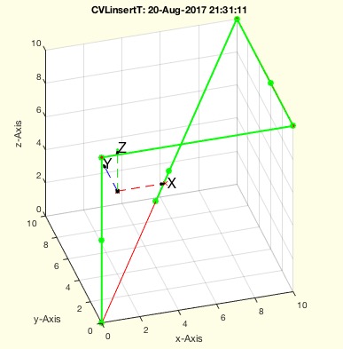 |
% CVLinsertT(CVL,T) - inserts the x/y crossing points of a CVL and a HT matrix of a plane % (by Tim Lueth, VLFL-Lib, 2017-AUG-20 as class: ANALYTICAL GEOMETRY) % % In case that a CVL should be cut by T matrix planes into two contour, % it is helpful to create and insert 3D splitpoint into the original CVL % (Status of: 2017-08-20) % % Introduced first in SolidGeometry 4.1 % % See also: CVLremstraightAmin % % NCVL=CVLinsertT(CVL,T) % === INPUT PARAMETERS === % CVL: CVL % T: T matrix % === OUTPUT RESULTS ====== % NCVL: NCVL matrix with crosing points with the xy plane % % EXAMPLE: % CVLinsertT(VLsample(8),TofP([2 4 5])) % % See also: CVLremstraightAmin % % % Copyright 2017 Tim C. Lueth |
exp_2017_08_21 (SG)- EXPERIMENT THAT IS IN FACT SGofCVLslices |
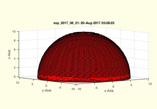 |
% exp_2017_08_21 (SG) - EXPERIMENT THAT IS IN FACT SGofCVLslices % (by Tim Lueth, VLFL-Lib, 2017-AUG-20 as class: EXPERIMENTS) % % Introduced first in SolidGeometry 4.1 % % See also: SGofCVLslices % % exp_2017_08_21([SG]) % === INPUT PARAMETERS === % SG: % % See also: SGofCVLslices % % % Copyright 2017 Tim C. Lueth |
SGseparatebyT(SG,T)- separates a solid into surfaces that are clearly below or above of a xy-plane |
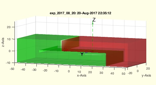 |
% SGseparatebyT(SG,T) - separates a solid into surfaces that are clearly below or above of a xy-plane % (by Tim Lueth, VLFL-Lib, 2017-AUG-20 as class: SURFACES) % % In contrast to SGcutT, when two solids are separated by a plane, this % fnctn SGseparatebyT raytraces the ez vector of T to identify solids % that are infront or behind the T coordinate system. It separates the % surfaces into "below", "above" or "undefined". % The solids of SGcutT would be considered as separated solids too. % (Status of: 2017-08-25) % % Introduced first in SolidGeometry 4.1 % % See also: SGsurfaces, SGcutT % % [SGX,SGA,SGB,SGC]=SGseparatebyT(SG,T) % === INPUT PARAMETERS === % SG: Solid Geoemtry % T: Separating frame/ plane % === OUTPUT RESULTS ====== % SGX: Surface that enclosed T (magenta); uncut % SGA: Surfaces clearly ABOVE T (red) % SGB: Surfaces clearly BELOW T (green) % SGC: Surfaces that below and above of T (white) % % EXAMPLE: % A=SGsample(5); T=TofP([0 0 3]); B=SGbladeofCVL(CVLofSGT(A,T),2,2); % A=SGboolTL(A,'-',B); SGseparatebyT(A,T) % % A=SGsample(5); T=TofP([0 0 3]); [A,B]=SGcutT(A,T); SGfigure; % SGplot(A,'r'); SGplot(B,'g'); % SGseparatebyT({A,B},T) % % SGseparatebyT(SGsample(5),T) % % See also: SGsurfaces, SGcutT % % % Copyright 2017 Tim C. Lueth |
VLFLofCVLdelaunay2D(CVL);- returns a triangulation for an almost planar CVL |
 |
% VLFLofCVLdelaunay2D(CVL); - returns a triangulation for an almost planar CVL % (by Tim Lueth, VLFL-Lib, 2017-AUG-20 as class: SURFACES) % % This fnctn works only for planar CVL (possible in different planes) and % if CVL contains only open contours and there is no curvature larger % than 90 degree. (Status of: 2017-08-28) % % Introduced first in SolidGeometry 4.1 % % See also: PLFLofCPLdelaunay % % [VL,FL]=VLFLofCVLdelaunay2D(CVL); % === INPUT PARAMETERS === % CVL): 3D closed contour vertex list % === OUTPUT RESULTS ====== % VL: Vertex list % FL: Facet List % % EXAMPLE: % VLFLofCVLdelaunay(VLsample(13)+5); % VLFLofCVLdelaunay(VLsample(19)+5); % % % See also: PLFLofCPLdelaunay % % % Copyright 2017 Tim C. Lueth |
SGbladeofCVL(CVL,sl,ad)- returns a solid for an almost planar CVL the closing facets |
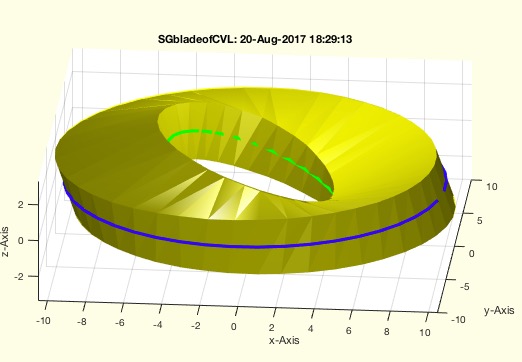 |
% SGbladeofCVL(CVL,sl,ad) - returns a solid for an almost planar CVL the closing facets % (by Tim Lueth, VLFL-Lib, 2017-AUG-20 as class: SURFACES) % % Introduced first in SolidGeometry 4.1 % % See also: VLFLofCVLdelaunay2D, SGofSurface % % SG=SGbladeofCVL(CVL,[sl,ad]) % === INPUT PARAMETERS === % CVL: Closed vertex list; open polygons % sl: Blade thickness; default=0.3 % ad: size growing; default=0; % === OUTPUT RESULTS ====== % SG: Solid Geometry of a blade % % EXAMPLE: % SGbladeofCVL(VLsample(19),3) % SGbladeofCVL([VLaddz(PLcircle(10));nan nan nan; % VLtransR(VLaddz(PLcircle(5)),rot(0,pi/8,0))],3) % % See also: VLFLofCVLdelaunay2D, SGofSurface % % % Copyright 2017 Tim C. Lueth |
TofT(T0,R,P)- returns a T matrix defined relative to another T matrix |
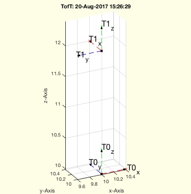 |
% TofT(T0,R,P) - returns a T matrix defined relative to another T matrix % (by Tim Lueth, VLFL-Lib, 2017-AUG-20 as class: ANALYTICAL GEOMETRY) % % This fnctn help to specify a new matrix relative to an existing one. % This is helpful to define cutting planes for SGcutT for example. % In fact it is the same as T1=T0*TofR(R,P) but may be easier to % understand. (Status of: 2017-08-20) % % Introduced first in SolidGeometry 4.1 % % See also: TofR, TofVL, TPL, TofDPhiH, T3ofT2, T3P, T2P, TofP, TofPez, % TofPEul % % T1=TofT(T0,[R,P]) % === INPUT PARAMETERS === % T0: Original Matrix % R: Rotation matrix relative to the T axis; scalar=phiz % P: Translation vector relative to the T axis; scalar=z % === OUTPUT RESULTS ====== % T1: resulting new T Matrix % % EXAMPLE: % TofT(TofP([10 10 10]),10) % TofT(TofP([10 10 10]),rot(0,0,pi)) % TofT(TofP([10 10 10]),pi/2,2) % % See also: TofR, TofVL, TPL, TofDPhiH, T3ofT2, T3P, T2P, TofP, TofPez, % TofPEul % % % Copyright 2017 Tim C. Lueth |
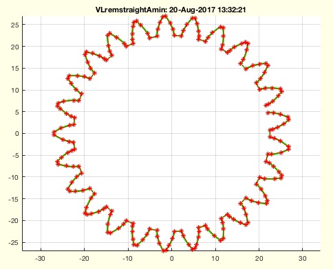
CVLremstraightAmin(CVL,Amin)- removes points with a minal distance/area to a predecessor or successor |
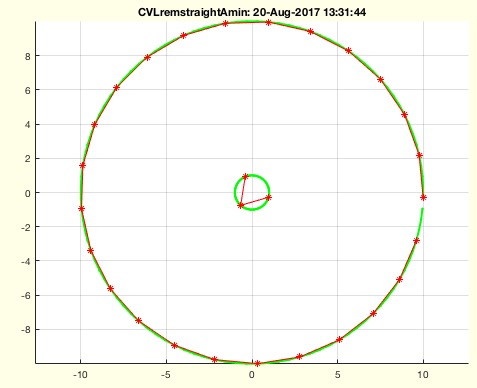 |
% CVLremstraightAmin(CVL,Amin) - removes points with a minal distance/area to a predecessor or successor % (by Tim Lueth, VLFL-Lib, 2017-AUG-20 as class: CLOSED POLYGON LISTS) % % This fnctn seperates individual CPLs by nan and processes them using % VLremstraightAmin The result is always an open end CPL! Ohter fnctn % such as CVLinsertT or CPLaddauxpoints insert additional points into a % contour (Status of: 2017-08-22) % % Introduced first in SolidGeometry 4.1 % % See also: VLremstraightAmin, CVLremstraight, CVLinsertT % % NVL=CVLremstraightAmin(CVL,[Amin]) % === INPUT PARAMETERS === % CVL: Closed Polygon Line in 2D or 3D % Amin: Minimal Area between two succeeding points; default is 1e-3; % === OUTPUT RESULTS ====== % NVL: New Vertex List % % EXAMPLE: % CVLremstraightAmin(VLaddz([PLcircle(10,100); nan % nan;PLcircle(1,100)]),1) % CVLremstraightAmin([PLcircle(10,100); nan nan;PLcircle(1,100)],1) % % See also: VLremstraightAmin, CVLremstraight, CVLinsertT % % % Copyright 2017 Tim C. Lueth |
VLremstraightAmin(CVL,Amin)- removes points with a minal distance/area to a predecessor or successor |
 |
% VLremstraightAmin(CVL,Amin) - removes points with a minal distance/area to a predecessor or successor % (by Tim Lueth, VLFL-Lib, 2017-AUG-19 as class: CLOSED POLYGON LISTS) % % VLremstraightCVL is an impressive simple but efficient method. % Nevertheless it fails if the point density is too tight. This fnctn % VLremstraightAmin adds the removal of each second (!) point that is too % tight. % The result is always open at the end! (Status of: 2017-08-20) % % Introduced first in SolidGeometry 4.1 % % See also: CVLremstraightAmin % % [NVL,ci]=VLremstraightAmin(CVL,[Amin]) % === INPUT PARAMETERS === % CVL: Closed Polygon Line in 2D or 3D % Amin: Minimal Area between two succeeding points; default is 1e-3; % === OUTPUT RESULTS ====== % NVL: New Vertex List % ci: mapping index from original to new % % EXAMPLE: % VL=VLaddz(PLcircle(1,10000)); VLremstraightAmin(roundn(VL,1e-7),1e-3); % VLremstraightAmin(VLaddz(PLsample(3)),1e-1); % VLremstraightAmin(VLaddz(CPLsample(19)),1e-1); % VLremstraightAmin(VLaddz(CPLsample(19)),1e-2 % VLremstraightAmin(VLaddz(VLsample(15)),1e-1); % VLremstraightAmin(VLaddz(CPLsample(21)),1e-1); % % See also: CVLremstraightAmin % % % Copyright 2017 Tim C. Lueth |
exp_2017_08_18- EXPERIMENT to show numerical resolution effects |
 |
% exp_2017_08_18 - EXPERIMENT to show numerical resolution effects % (by Tim Lueth, VLFL-Lib, 2017-AUG-19 as class: EXPERIMENTS) % % Introduced first in SolidGeometry 4.1 % % See also: VLremstraightAmin, CVLremstraightAmin % % exp_2017_08_18 % % See also: VLremstraightAmin, CVLremstraightAmin % % % Copyright 2017 Tim C. Lueth |
epsofVL(NVL,n)- returns the minimal points distance in a set of vertices or two groups |
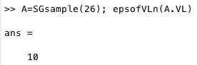 |
% epsofVL(NVL,n) - returns the minimal points distance in a set of vertices or two groups % (by Tim Lueth, VLFL-Lib, 2017-AUG-17 as class: AUXILIARY PROCEDURES) % % The fnctn can also be called using two VL or two SG. The fnctn has % quadratic effort. It wil become very slow for large vertex lists. % (Status of: 2017-08-17) % % Introduced first in SolidGeometry 4.1 % % See also: eps, eps2 % % [e,ea,eb]=epsofVL(NVL,[n]) % === INPUT PARAMETERS === % NVL: Vertex list with appended split points % n: number to split the vertex list into 2 parts [1:n,:] & [n+1:end,:] % === OUTPUT RESULTS ====== % e: smallest number larger 0 between the points % ea: epsilon within the first group % eb: epsilon within the second group % % EXAMPLE: % A=SGsample(5); SGfigure(A); view(-30,30); epsofVL(A.VL) % A=SGsample(26); SGfigure(A); view(-30,30); epsofVL(A.VL) % A=SGsample(25); SGfigure(A); view(-30,30); epsofVL(A.VL) % A=SGsample(5); SGfigure(A); view(-30,30); [a,b,c]=epsofVL(A.VL,500) % A=SGsample(26); SGfigure(A); view(-30,30); [a,b,c]=epsofVL(A.VL,5) % % See also: eps, eps2 % % % Copyright 2017 Tim C. Lueth |
FLunique(FL)- returns a FL without copies of circshifted rows |
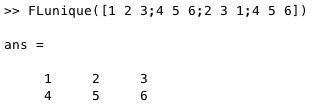 |
% FLunique(FL) - returns a FL without copies of circshifted rows % (by Tim Lueth, VLFL-Lib, 2017-AUG-17 as class: SURFACES) % % Introduced first in SolidGeometry 4.1 % % See also: ELunique, ELuniqueofFL % % FL=FLunique(FL) % === INPUT PARAMETERS === % FL: Facet list % === OUTPUT RESULTS ====== % FL: Facet list with unique rows; % % EXAMPLE: % FLunique([1 2 3;4 5 6;2 3 1;4 5 6]) % % See also: ELunique, ELuniqueofFL % % % Copyright 2017 Tim C. Lueth |
VLmindist(VL,epsr)- returns the minimal distance larger than zero |
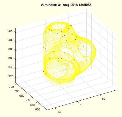 |
% VLmindist(VL,epsr) - returns the minimal distance larger than zero % (by Tim Lueth, VLFL-Lib, 2017-AUG-17 as class: ANALYTICAL GEOMETRY) % % After reading in a STL file, there is a need to check the minmal % distances between the vertices. % If the minimal distance is smaller than the minimal value of Matlab, % eps, accuracy errors will occur. (Status of: 2018-08-31) % % Introduced first in SolidGeometry 4.1 % % See also: eps, eps2, epsdyn, VLmindxyz, SGshortopti, % VLcheckvertexaccuracy % % [dmm,dmin]=VLmindist(VL,[epsr]) % === INPUT PARAMETERS === % VL: vector list % epsr: optional rounding before; default is 0, i.e. no rounding % === OUTPUT RESULTS ====== % dmm: absolute minimal distance % dmin: minmal distance per column % % EXAMPLE: % VLmindist(rand(1000000,1)) % linear minimal random distance % VLmindist(rand(1000000,2)) % quadratic minimal random distance % VLmindist(rand(1000000,3)) % cubic minimal random distance % % loadweb JACO_robot.mat % VLmindist(JC61.VL) % % See also: eps, eps2, epsdyn, VLmindxyz, SGshortopti, % VLcheckvertexaccuracy % % % Copyright 2017-2018 Tim C. Lueth |
SGplotparts(A,c,Fs,si)- plots the overlapping parts of a solid separately |
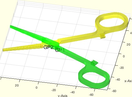 |
% SGplotparts(A,c,Fs,si) - plots the overlapping parts of a solid separately % (by Tim Lueth, VLFL-Lib, 2017-AUG-16 as class: SURFACES) % % The result of SGanalyzeGroupParts is a struct with a field SG. It % contains overlapping objects that form a melted/joined solid and could % be group melted (Status of: 2017-08-16) % % Introduced first in SolidGeometry 4.1 % % See also: SGanalyzeGroupParts, SGplot, SGplotsurfaces % % h=SGplotparts(A,[c,Fs,si]) % === INPUT PARAMETERS === % A: Solid or Group Part Solid (A.SG) % c: color or colorstring such as 'rbwcr' % Fs: Font size for Descriptor; default is 16 % si: selector for group parts % === OUTPUT RESULTS ====== % h: handle to graphic objects % % EXAMPLE: close all; SGfigure; view(30,30); SGplotparts(SGsample(17)); % GP=SGanalyzeGroupParts(SGsample(17)); % close all; SGfigure; view(30,30); SGplotparts(GP); % close all; SGfigure; view(30,30); SGplotparts(GP,'wr'); % close all; SGfigure; view(30,30); SGplotparts(GP,'wr',20); % close all; SGfigure; view(30,30); SGplotparts(GP,'wr',20,1); % close all; SGfigure; view(30,30); SGplotparts(GP,'wr',20,2); % % See also: SGanalyzeGroupParts, SGplot, SGplotsurfaces % % % Copyright 2017 Tim C. Lueth |
SGplotsurfaces(SG,col,Fs,si)- plots closed surface of the solids seperatly in different colors |
 |
% SGplotsurfaces(SG,col,Fs,si) - plots closed surface of the solids seperatly in different colors % (by Tim Lueth, VLFL-Lib, 2017-AUG-16 as class: USER INTERFACE) % % very similar to SGsurfaceplot, but more a clear plotting fnctn % (Status of: 2017-08-16) % % Introduced first in SolidGeometry 4.1 % % See also: SGseparate % % h=SGplotsurfaces(SG,[col,Fs,si]) % === INPUT PARAMETERS === % SG: Solid Geoemtry % col: color force; default is ''; % Fs: Font size for descriptors; default is 0 % si: surface selectors % === OUTPUT RESULTS ====== % h: handle to drawing % % See also: SGseparate % % % Copyright 2017 Tim C. Lueth |
SGchamfer(SG,ph,ed,r,stype,posit,shape,hole)- chamfers the edges of a 2.5D Solid Geometry |
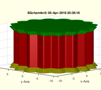 |
% SGchamfer(SG,ph,ed,r,stype,posit,shape,hole) - chamfers the edges of a 2.5D Solid Geometry % (by Tim Lueth, VLFL-Lib, 2017-AUG-16 as class: SURFACES) % % Optimized in Dakhla, Marocco. It does not returns as perfect edges as % SGofCPLzchamfer but is the same as SGchamfer! Used first with negative % values by Samuel Detzel! % if r>0; r must be larger than abs(ph)*1.5 % ATTENTION: If r is reduced automatically by tangentcirc, ph can be only % r/1.5, or r must be zero! (Status of: 2018-04-16) % % Introduced first in SolidGeometry 4.1 % % See also: PLchamfer, SGofCPLzchamfer, SGof2CPLzheurist, CPLradialEdges % % SGN=SGchamfer(SG,[ph,ed,r,stype,posit,shape,hole]) % === INPUT PARAMETERS === % SG: Solid Geometry with just two different z values % ph: edge/phase size default is 0.3; [r z], [r zs ze] is also valid % ed: curved edges; default is true % r: radius for radial edges; default is ph*1.5 % stype: default is 'angle'; see SGof2CPLzheurist % posit: 'both', 'start', 'end' or calculated from ph % shape: PL or 'line' (default), 'circ', see PLchamfer for all values % hole: "norm", "outw", "hole", see CPLgrow for all values % === OUTPUT RESULTS ====== % SGN: % % EXAMPLE: % SGchamfer(SGsample(2)) % SGchamfer(SGofCPLz(PLcircleoval(10,'',20,5),10)) % SGchamfer(SGofCPLz(PLstar(10),10),0.3,'') % SGchamfer(SGofCPLz(PLstar(10),10),0.3,'',2) % SGchamfer(SGofCPLz(PLstar(10),10),0.3,'',-0.5) % SGchamfer(SGofCPLz(PLstar(10),10),-1) % SGchamfer(SGlinkage(5,30,10),0.3) % SGchamfer(SGsample(10),-2,false,0) % SGchamfer(SGsample(10),-2,true,0) % SGchamfer(SGsample(10),-2,true,0,'center') % % See also: PLchamfer, SGofCPLzchamfer, SGof2CPLzheurist, CPLradialEdges % % % Copyright 2017-2018 Tim C. Lueth |
SGbladeofPL(sl,XZL,YZL,T,XSG)- returns a solid with a shape of a cutting blade in z direction |
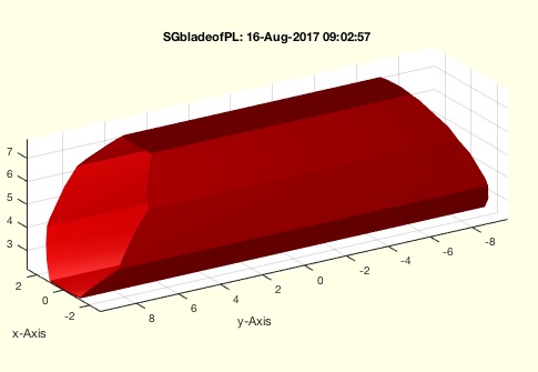 |
% SGbladeofPL(sl,XZL,YZL,T,XSG) - returns a solid with a shape of a cutting blade in z direction % (by Tim Lueth, VLFL-Lib, 2017-AUG-16 as class: SURFACES) % % This fnctn create a big variety of blade structures depending on the % input values; % (Status of: 2017-08-16) % % Introduced first in SolidGeometry 4.1 % % See also: SGbool, SGinsertCut, SGcutBB, SGinsertPeghole % % SG=SGbladeofPL([sl,XZL,YZL,T,XSG]) % === INPUT PARAMETERS === % sl: thickness of the blade % XZL: z or [x z] or PL with xz values; % YZL: depth in Y % T: Transformation Matrix % XSG: Final Crossing Solid to limit the outer shape % === OUTPUT RESULTS ====== % SG: Cutting Blade Slid Geometry % % EXAMPLE: % SGbladeofPL(3,10) % SGbladeofPL(0.5,10) % SGbladeofPL(1,[10,10]) % SGbladeofPL(0.05,PLcircle(10)) % SGbladeofPL(0.05,CPLofPL(PLcircle(10))) % A=SGbladeofPL(0.5,CPLofPL(PLcircle(3)),30,TofP([0 0 5])); % SGboolTL(SGsample(5),'-',A) % SGbladeofPL(0.05,CPLofPL(PLcircle(3,8)),30,TofP([0 0 5]),SGsample(5)); % % See also: SGbool, SGinsertCut, SGcutBB, SGinsertPeghole % % % Copyright 2017 Tim C. Lueth |
SGboolTL(A,op,B,Amin)- returns a Boolean operation including re T esse L ation |
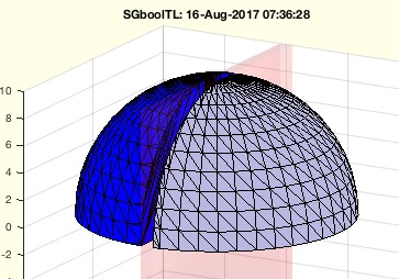 |
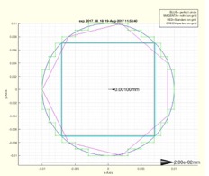
% SGboolTL(A,op,B,Amin) - returns a Boolean operation including re T esse L ation % (by Tim Lueth, VLFL-Lib, 2017-AUG-16 as class: SURFACES) % % This fnctn calls SGbool but performs preprocessing and postprocessing. % The syntax is changed from (Operation, A, B) to (A, Operation, B) % 1. Both argoment solids and the resulting solids get a retesselation % using a minimal facet area of Amin % 2. Argument Solid B is grown by 1e-5 % This is done to make sure that identical points,faces, solids can be % processed. % If SGbool fails, there is always a numerical problem. % The retesselation will create sometimes faces of a minimal area just to % turn the edges of some facets. This is a principal problem until a % global retesselation solution is implemented if exists at all. % % This fnctn will be integrated into SGbool soon, since the type of the % second argument will help to distinguish between two types: % SGbool ('+',A,B) or SGbool(A,'+',B) ==> SGboolTL(A,'+',B) % % BTW: CATIA LIMITS THE SPATIAL RESOLUTION TO 0.01mm, ie. 1e-2 % (Status of: 2017-08-16) % % Introduced first in SolidGeometry 4.1 % % See also: SGbool, SGretesselate, SGgrow % % SG=SGboolTL(A,op,B,[Amin]) % === INPUT PARAMETERS === % A: Solid A % op: Boolean Operator % B: Solid B % Amin: Minimal Area for tessealtion; default 0.01 % === OUTPUT RESULTS ====== % SG: % % EXAMPLE: % A=SGsample(26); SGboolTL(A,'+',SGtransP(A,[0 0 10])) % A=SGsample(5); B=SGbox([1,20,20]); SGboolTL(A,'-',B); % A=SGsample(27); B=SGbox([1,20,20]); SGboolTL(A,'-',B); % A=SGsample(5); B=SGbox([1,15,15]); SGboolTL(A,'-',B); % A=SGsample(26); B=SGoftext('TIM',[20,4,2]); % SGboolTL(A,'-',SGtransrelSG(B,A,'center','aligntop',1)); % % See also: SGbool, SGretesselate, SGgrow % % % Copyright 2017 Tim C. Lueth |
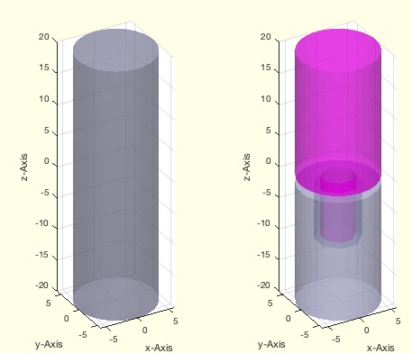
SGinsertPeghole(SG,T,sl,sx,ad)- returns a solid with an inserted peg and hole connector |
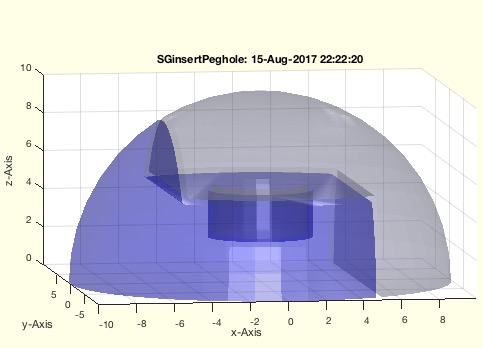 |
% SGinsertPeghole(SG,T,sl,sx,ad) - returns a solid with an inserted peg and hole connector % (by Tim Lueth, VLFL-Lib, 2017-AUG-15 as class: SURFACES) % % After cutting an object using (Status of: 2017-08-15) % % Introduced first in SolidGeometry 4.1 % % See also: SGbool, SGinsertCut, SGcutBB % % [SG,T,d]=SGinsertPeghole(SG,[T,sl,sx,ad]) % === INPUT PARAMETERS === % SG: Solid Geometry % T: Separation plane % sl: slot size peg and hole % sx: diameter of slot size; or CPL of peg % ad: doubled length of peg % === OUTPUT RESULTS ====== % SG: Solid Geometry with a peg and a hole % T: % d: % % EXAMPLE: % [X,T]=SGinsertCut(SGsample(5),eye(4),0.3,10) % SGinsertPeghole(X,T,0.3,10,) % SGinsertPeghole(X,T,0.3,10,5) % SGinsertPeghole(X,T,0.3,PLcircle(3,4),5) % % See also: SGbool, SGinsertCut, SGcutBB % % % Copyright 2017 Tim C. Lueth |
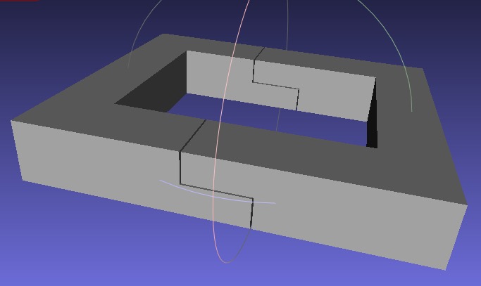
SGinsertCut(SG,T,sl,sx,ad)- returns a solid with an inserted cut |
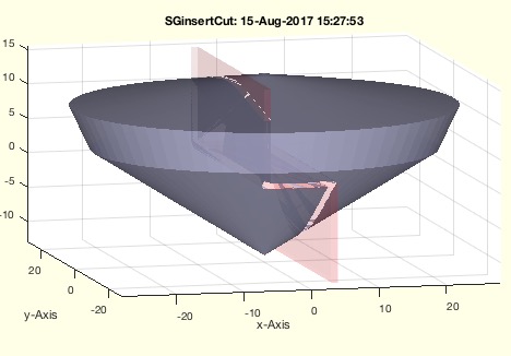 |
% SGinsertCut(SG,T,sl,sx,ad) - returns a solid with an inserted cut % (by Tim Lueth, VLFL-Lib, 2017-AUG-15 as class: SURFACES) % % Introduced first in SolidGeometry 4.1 % % See also: SGbool, SGcutBB % % [SG,T,d]=SGinsertCut(SG,[T,sl,sx,ad]) % === INPUT PARAMETERS === % SG: Solid Geometry % T: Transformation for cut; default is eye(4) % sl: cut slot size; default is 0.3 % sx: transversal separation of cut; default is 0; % ad: addendum ; default is 1 mm; tbi: if negative add is added to bb of % SG % === OUTPUT RESULTS ====== % SG: Solid Geoemtry, retesselated Amin=0.01 % T: exact cutting point matrix % d: distance values relative to T % % EXAMPLE: % SGinsertCut(SGsample(5),'',1,4) % SGinsertCut(SGsample(5),'','',4) % SGinsertCut(SGsample(5),'','','') % SGinsertCut(SGsample(5),'','','',5) % SGinsertCut(SGsample(5),TofR(rot(0,0,pi/4)),'','',5) % % See also: SGbool, SGcutBB % % % Copyright 2017 Tim C. Lueth |
VLFLfreeboundary(VL,FL)- returns the freeboundary of a solid |
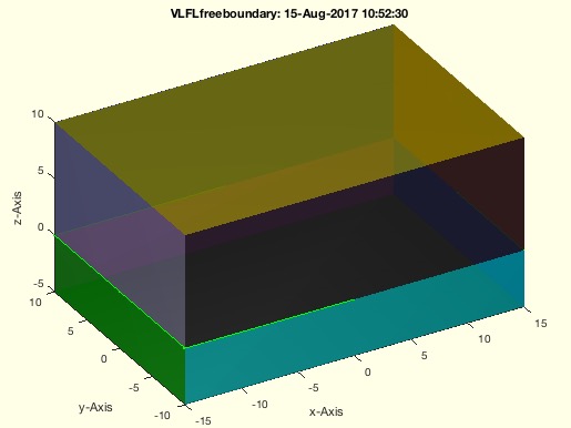 |
% VLFLfreeboundary(VL,FL) - returns the freeboundary of a solid % (by Tim Lueth, VLFL-Lib, 2017-AUG-15 as class: SURFACES) % % Same as fnctn freeBoundary. There is a difference to ELboundaryFL or % ELofFLborder, since a triangualtion is created first that detects % doubled vertices. (Status of: 2017-08-15) % % Introduced first in SolidGeometry 4.1 % % See also: VLFLplotfreeboundary, ELboundaryFL, ELofFLborder % % EL=VLFLfreeboundary(VL,FL) % === INPUT PARAMETERS === % VL: Vertex list or Solid Geoemtry % FL: Facet List or empty % === OUTPUT RESULTS ====== % EL: Edge list % % See also: VLFLplotfreeboundary, ELboundaryFL, ELofFLborder % % % Copyright 2017 Tim C. Lueth |
PLgrowline(PL,s,edge);- converts a single open polygon into a grown contour |
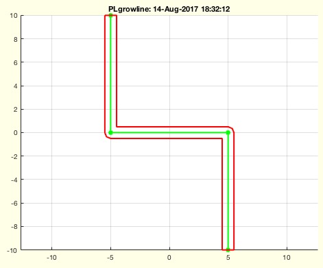 |
% PLgrowline(PL,s,edge); - converts a single open polygon into a grown contour % (by Tim Lueth, VLFL-Lib, 2017-AUG-14 as class: CLOSED POLYGON LISTS) % % Introduced first in SolidGeometry 4.1 % % See also: PLgrow, CPLgrow % % CPL=PLgrowline(PL,s,[edge]); % === INPUT PARAMETERS === % PL: Open point list line % s: thickness % edge: true= rounded edges; false = simple; % === OUTPUT RESULTS ====== % CPL: Closed Polygon line % % EXAMPLE: % PL=[-5 10; -5 0; +5 0; +5 -10] % PLgrowline(PL,1,true) % PLgrowline(PL,1,false) % % See also: PLgrow, CPLgrow % % % Copyright 2017 Tim C. Lueth |
VLFLfaceAngles(VL,FL,thr)- returns the three angles for the facets of a solid |
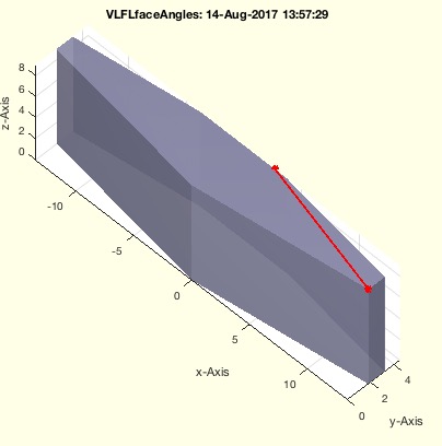 |
% VLFLfaceAngles(VL,FL,thr) - returns the three angles for the facets of a solid % (by Tim Lueth, VLFL-Lib, 2017-AUG-14 as class: SURFACES) % % Introduced first in SolidGeometry 4.1 % % See also: VLFLfaceNormal % % [FLa,ma]=VLFLfaceAngles(VL,FL,[thr]) % === INPUT PARAMETERS === % VL: Vertex list % FL: Facet list % thr: threshold; default is eps2 % === OUTPUT RESULTS ====== % FLa: angle 1 2 3; [nf x 3] % ma: minimal value angles [nf] % % EXAMPLE: % [VL,FL]=SGsample(30); VLFLfaceAngles (VL,FL); % [VL,FL]=SGsample(30); VLFLfaceAngles (VL,FL,1e-5); % [VL,FL]=SGsample(30); VLFLfaceAngles (VL,FL,1e-4); % [VL,FL]=SGsample(30); VLFLfaceAngles (VL,FL,1e-3); % [VL,FL]=SGsample(30); VLFLfaceAngles (VL,FL,1e-2); % [VL,FL]=SGsample(30); VLFLfaceAngles (VL,FL,1e-1); % [VL,FL]=SGsample(30); VLFLfaceAngles (VL,FL,1e-0); % % See also: VLFLfaceNormal % % % Copyright 2017 Tim C. Lueth |
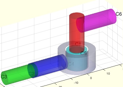
SGboolanalyze(A,B,thr)- plots the two separated surfaces of A and B when crossed |
 |
% SGboolanalyze(A,B,thr) - plots the two separated surfaces of A and B when crossed % (by Tim Lueth, VLFL-Lib, 2017-AUG-14 as class: SURFACES) % % This fnctn show the principles of SGintersectFacetPoints, % VLFLinsertFacetPoints, SGisInterior and SGbool. (Status of: 2017-08-14) % % Introduced first in SolidGeometry 4.1 % % See also: SGintersectFacetPoints, VLFLinsertFacetPoints, SGisInterior, % SGbool % % SGboolanalyze(A,B,[thr]) % === INPUT PARAMETERS === % A: Solid A; or number for CSGsample % B: Solid B; % thr: % % EXAMPLE: % SGboolanalyze(8) % % See also: SGintersectFacetPoints, VLFLinsertFacetPoints, SGisInterior, % SGbool % % % Copyright 2017 Tim C. Lueth |
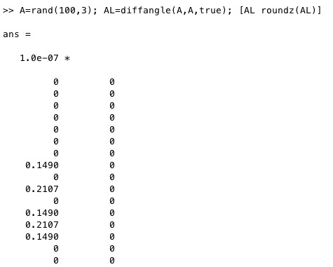
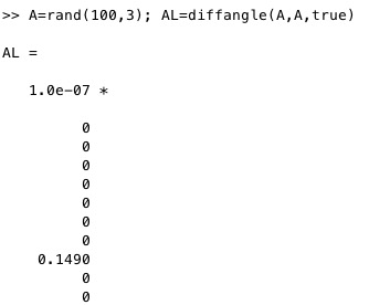
eps2- returns the rounding limit for triangular or quadratic problems |
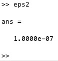 |
% eps2 - returns the rounding limit for triangular or quadratic problems % (by Tim Lueth, VLFL-Lib, 2017-AUG-14 as class: AUXILIARY PROCEDURES) % % While fnctn eps returns the minimal distance between zero and a floting % points number, % eps 2 returns the root of this number. Therefor eps is a candidate to % round fnctns such as acos, cross, etc. (Status of: 2017-08-14) % % Introduced first in SolidGeometry 4.1 % % See also: eps, roundn, acos, cross % % to=eps2 % === OUTPUT RESULTS ====== % to: rounding limit for square problems % % EXAMPLE: % eps2 % VL=rand(100,3); VL=normr(VL); dp=bsxfun(@dot,VL',VL')'; % a=real(acos(dp)); [a roundz(a,eps2)] % % See also: eps, roundn, acos, cross % % % Copyright 2017 Tim C. Lueth |
SGbooltest(tests)- Procedure to test different cases using SGbool and CSGsample |
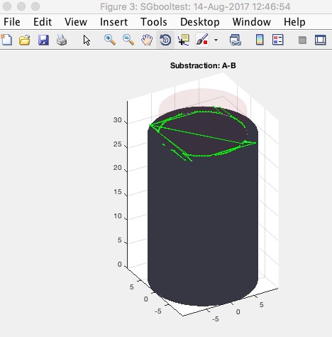 |
VLiscollBBs(bba,VL)- returns the crossing of a vertex list with bounding boxes list |
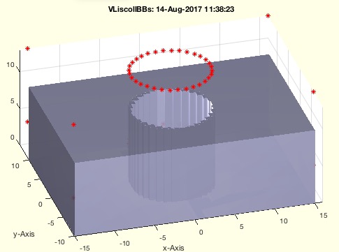 |
% VLiscollBBs(bba,VL) - returns the crossing of a vertex list with bounding boxes list % (by Tim Lueth, VLFL-Lib, 2017-AUG-14 as class: ANALYZING PROCEDURES) % % This fnctn can be used directly to preprocess, i.e. accelerate facet % crossing fnctns (Status of: 2017-08-14) % % Introduced first in SolidGeometry 4.1 % % See also: VLDLBBofVLFL, collofBBs % % [CL,ca,cb]=VLiscollBBs(bba,VL) % === INPUT PARAMETERS === % bba: bounding box list A or Solid Geometry % VL: Vertex list to test % === OUTPUT RESULTS ====== % CL: Crossing list [n x 2] = [ia ib] % ca: A % cb: optional index list of crossings of VL % % EXAMPLE: % [A,B]=CSGsample(5); VLiscollBBs(A,B.VL) % [A,B]=CSGsample(5); VLiscollBBs(A,A.VL) % % See also: VLDLBBofVLFL, collofBBs % % % Copyright 2017 Tim C. Lueth |
VLFLfreeboundaryfacets(VL,FL,thr)- returns the facets attached to the freeboundary edges |
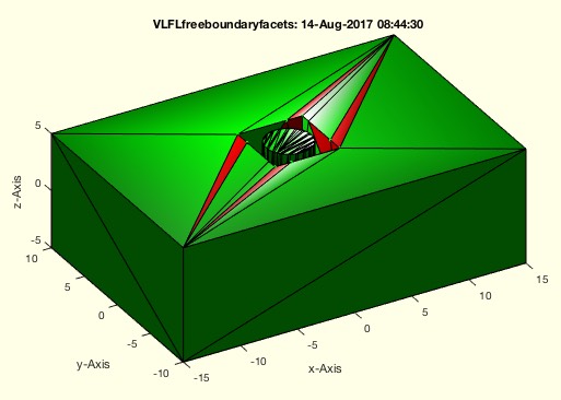 |
% VLFLfreeboundaryfacets(VL,FL,thr) - returns the facets attached to the freeboundary edges % (by Tim Lueth, VLFL-Lib, 2017-AUG-14 as class: SURFACES) % % During testing of SGbool it became obvious, that the result of SGbool % without a postprocessing will create structures that MATLAB's % triangulation procedure will consider as open edge structure while % Meshlab would consider it as perfect solid. % Those tests where performed using % 1. A 1e-12 grid on both solids! % 2. Non rounding during SGintersectFacetPoints % 3. Thresholds of 1e-6 for VL and 1e-9 for NPLs % 4. Thresholds for 1e-6 for UVP and added triangulation points % 5. Thresholds of 1e-6 for minimal area of a facet (line type) % Even than, there are problems with surface that come from the fnctn % SGisinterior, since there is a bug for coordinates ontop of barycentric % coordinates % A final fusion of 1e-8 on the point position solves this problem. % Therefore Meshlab roundes at least at 1e-8 / and the accuracy of SGbool % is maximum 1e-8; % % (Status of: 2017-08-15) % % Introduced first in SolidGeometry 4.1 % % See also: VLFLplotfreeboundary % % [FL,EL]=VLFLfreeboundaryfacets(VL,FL,[thr]) % === INPUT PARAMETERS === % VL: Vertex list % FL: Facet list % thr: threshold for VLFLshort2; default is 0; % === OUTPUT RESULTS ====== % FL: facets attached to the freeboundary edges % EL: freeboundary edges % % See also: VLFLplotfreeboundary % % % Copyright 2017 Tim C. Lueth |
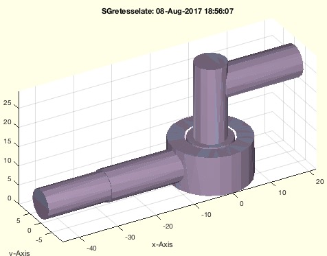
SGinsertJoint(SG,T,typ,x)- creates joint structures inside of a solid geometry |
 |
% SGinsertJoint(SG,T,typ,x) - creates joint structures inside of a solid geometry % (by Tim Lueth, VLFL-Lib, 2017-AUG-13 as class: SURFACES) % % Introduced first in SolidGeometry 4.1 % % SGR=SGinsertJoint(SG,T,typ,x) % === INPUT PARAMETERS === % SG: Solid Geometry % T: Frame for the Solid Geometry % typ: Type of joint % x: parameter set % === OUTPUT RESULTS ====== % SGR: % % EXAMPLE: % SG=SGsample(29); SGinsertJoint(SG,TofR(rot(0,0,0),[0 +20 5])); % % % Copyright 2017 Tim C. Lueth |
VLFLplotfreeboundary(VL,FL,c,w)- plots the freeboundary of a solid with grid forced vertices (1e-6) |
 |
% VLFLplotfreeboundary(VL,FL,c,w) - plots the freeboundary of a solid with grid forced vertices (1e-6) % (by Tim Lueth, VLFL-Lib, 2017-AUG-13 as class: USER INTERFACE) % % Points that have coordinate differences of less than 1e-6 are mapped to % the same vertices in the triangulation class. Therefor the threshold in % this fnctn is 1e-6; (Status of: 2017-08-15) % % Introduced first in SolidGeometry 4.1 % % See also: VLFLfreeboundary, VLFLplots, VLELplot, VLFLplot, % VLFLfreeboundaryfacets % % h=VLFLplotfreeboundary(VL,FL,[c,w]) % === INPUT PARAMETERS === % VL: Vertex list % FL: Facet list % c: color; default is 'r-' % w: width of lines % === OUTPUT RESULTS ====== % h: handle to the drawings % % EXAMPLE: % [A,B]=CSGsample(8); SGbool('A',A,B); X=ans; % VLFLplotfreeboundary(X.VL,X.FL); % % See also: VLFLfreeboundary, VLFLplots, VLELplot, VLFLplot, % VLFLfreeboundaryfacets % % % Copyright 2017 Tim C. Lueth |
roundz(x,thr)- returns zeros if a number is larger than -thr and smaller than thr |
 |
% roundz(x,thr) - returns zeros if a number is larger than -thr and smaller than thr % (by Tim Lueth, VLFL-Lib, 2017-AUG-12 as class: AUXILIARY PROCEDURES) % % ======================================================================= % OBSOLETE (2017-08-12) - USE FAMILY 'roundn' INSTEAD % ======================================================================= % % roundn is twice as fast as roundz! Therefore use roundn % At lot of trigonometric fnctn and cross product or dot product have % problems with numerical accuracy. % Double = rounds(1,12) % single = rounds(1,6) % half = rounds(1,3) (Status of: 2017-08-12) % % Introduced first in SolidGeometry 4.1 % % See also: [ roundn ] ; round, roundn % % y=roundz(x,[thr]) % === INPUT PARAMETERS === % x: floating point number % thr: threshold % === OUTPUT RESULTS ====== % y: small numbers are set to zero % % EXAMPLE: % VL=rand(100,3); VL=normr(VL); dp=bsxfun(@dot,VL',VL')'; % a=real(acos(dp)); [a roundz(a,1e-6)] % % See also: [ roundn ] ; round, roundn % % % Copyright 2017 Tim C. Lueth |
rounds(x,s)- is just an abbreviation if rounds(x,s,'significant') |
 |
% rounds(x,s) - is just an abbreviation if rounds(x,s,'significant') % (by Tim Lueth, VLFL-Lib, 2017-AUG-12 as class: AUXILIARY PROCEDURES) % % At lot of trigonometric fnctn and cross product or dot product have % problems with numerical accuracy. % Double = rounds(1,12) % single = rounds(1,6) % half = rounds(1,3) (Status of: 2017-08-12) % % Introduced first in SolidGeometry 4.1 % % See also: round, roundn % % y=rounds(x,s) % === INPUT PARAMETERS === % x: floating point number % s: number of % === OUTPUT RESULTS ====== % y: rounded x % % See also: round, roundn % % % Copyright 2017 Tim C. Lueth |
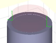
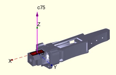
crosspointsVLFLofT(VL,FL,T,)- returns the crossing points of the axis of a coordinate system |
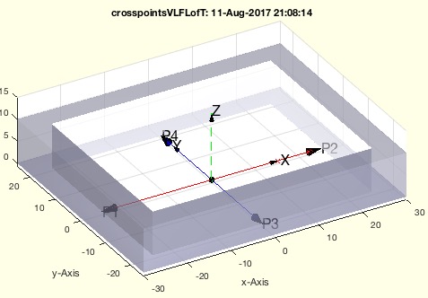 |
% crosspointsVLFLofT(VL,FL,T,) - returns the crossing points of the axis of a coordinate system % (by Tim Lueth, VLFL-Lib, 2017-AUG-11 as class: KINEMATICS AND FRAMES) % % For a rotational axis, typically the z values TVL(5:6,:) are important % For a prismatic axis, typically the x axis TVL(1:2) is important % (Status of: 2017-08-12) % % Introduced first in SolidGeometry 4.1 % % See also: crosspointVLFL, CVLofSGcutplanes, CVLofconvexHull % % [TVL,td,np,TN]=crosspointsVLFLofT(VL,FL,T,[]) % === INPUT PARAMETERS === % VL: Vertex List of Solid % FL: Facet List of Solid % T: Coordinate Frame [4x4] % === PROPERTY NAMES ===== % 'center' : if 'center' is used; the Matrix TN contains the moved frame % matrix % === OUTPUT RESULTS ====== % TVL: Touch vertex list [6 x 3] % td: distances between touch points [dx dy dz] % np: center of crossing lines % TN: Optional moved Frame matrix % % EXAMPLE: % VL,FL]=SGsample(5);crosspointsVLFLofT(VL,FL,eye(4)) % VL,FL]=SGsample(29); % crosspointsVLFLofT(VL,FL,TofR(rot(0,0,0),[0 22 5])) % crosspointsVLFLofT(VL,FL,TofR(rot(0,pi/4,0),[0 22 5])) % % See also: crosspointVLFL, CVLofSGcutplanes, CVLofconvexHull % % % Copyright 2017 Tim C. Lueth |
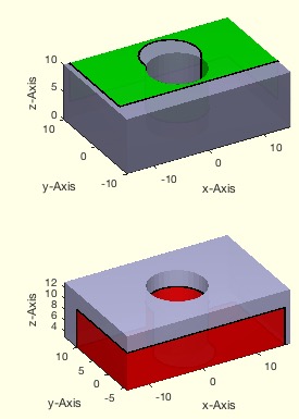
CVLofSGcutplanes(SG,T)- returns the three cutting contours at a frame coordinate system through a solid |
 |
% CVLofSGcutplanes(SG,T) - returns the three cutting contours at a frame coordinate system through a solid % (by Tim Lueth, VLFL-Lib, 2017-AUG-11 as class: EXPERIMENTS) % % Thus fnctn helps to create cutting contours for a solid using an % optional cutting frame coordinate system. In contrast to % CVLofconvexHull, this fnctn create a local cut that is only considering % the solid space around the frame coordinate system (Status of: % 2017-08-11) % % Introduced first in SolidGeometry 4.1 % % See also: CVLofconvexHull, CVLofSGcutT, CVLofSGT % % [CVLX,CVLY,CVLZ,SG2]=CVLofSGcutplanes(SG,T) % === INPUT PARAMETERS === % SG: Solid geoemtry % T: cutting coordinate system; must be inside of the solid! % === OUTPUT RESULTS ====== % CVLX: cutting contour x=0 (green) % CVLY: cutting contour y=0 (blue) % CVLZ: cutting contour z=0 (red) % SG2: used T matrix; if input parameter T was empty % % EXAMPLE: % CVLofSGcutplanes(SGsample(29)) % CVLofSGcutplanes(SGsample(30)) % CVLofSGcutplanes(SGsample(29),TofP([0 22 5])) % CVLofSGcutplanes(SGsample(29),TofR(rot(pi/20,pi/20,pi/20),[0 22 5])) % % See also: CVLofconvexHull, CVLofSGcutT, CVLofSGT % % % Copyright 2017 Tim C. Lueth |
CVLofconvexHull(SG,T)- returns the three cutting contours through the convex hull of a solid |
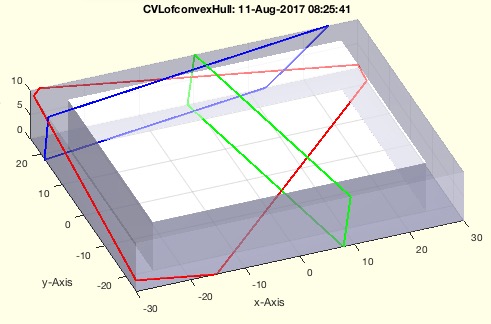 |
% CVLofconvexHull(SG,T) - returns the three cutting contours through the convex hull of a solid % (by Tim Lueth, VLFL-Lib, 2017-AUG-11 as class: EXPERIMENTS) % % Thus fnctn helps to create cutting contours for a solid using an % optional cutting frame coordinate system (Status of: 2017-08-11) % % Introduced first in SolidGeometry 4.1 % % [CVLX,CVLY,CVLZ,T]=CVLofconvexHull(SG,[T]) % === INPUT PARAMETERS === % SG: Solid geoemtry % T: cutting coordinate system; default is eye(4) at center of solid % === OUTPUT RESULTS ====== % CVLX: cutting contour x=0 (green) % CVLY: cutting contour y=0 (blue) % CVLZ: cutting contour z=0 (red) % T: used T matrix; if input parameter T was empty % % EXAMPLE: % CVLofconvexHull(SGsample(29)) % CVLofconvexHull(SGsample(30)) % CVLofconvexHull(SGsample(29),TofP([0 22 5])) % CVLofconvexHull(SGsample(29),TofR(rot(pi/20,pi/20,pi/20),[0 22 5])) % % % Copyright 2017 Tim C. Lueth |
textVLFS(VL,FL,FSi,c,s,nt,lb)- plots descriptors for each feature surface and the corresponding feature edges |
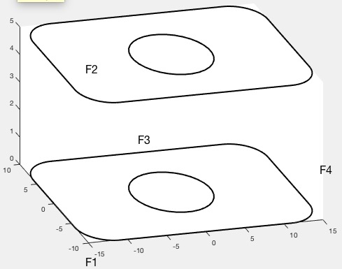 |
% textVLFS(VL,FL,FSi,c,s,nt,lb) - plots descriptors for each feature surface and the corresponding feature edges % (by Tim Lueth, VLFL-Lib, 2017-AUG-10 as class: VISUALIZATION) % % This is an auxiliary fnctn to the boundaries of feature surfaces and % the feature surface descriptors % In contrast to FSplot, the surfaces itself are not drawn (Status of: % 2017-08-10) % % Introduced first in SolidGeometry 4.1 % % See also: FSplot, textT, textP, textVL, textCVL, textVLFL, % VLFLfaceNormalplot % % h=textVLFS(VL,FL,FSi,[c,s,nt,lb]) % === INPUT PARAMETERS === % VL: Vertex list % FL: Facet List % FSi: Feature surface index list; FSi = surfacesofSG(SG,fea); % c: Color, default is black % s: Size, default is 10 % nt: optional list of selected points % lb: optional string for text; default is 'F' % === OUTPUT RESULTS ====== % h: handle to modify or delete text if necessary % % EXAMPLE: % close all; SG=SGsample(27); fea=0.08; FSi=surfacesofSG(SG,fea); % SGfigure; view(-30,30); h=SGplot(SG); setplotlight(h,'w',0.9); % textVLFS(SG.VL,SG.FL,FSi); % % See also: FSplot, textT, textP, textVL, textCVL, textVLFL, % VLFLfaceNormalplot % % % Copyright 2017 Tim C. Lueth |
TofFS(TR,Nr,fe,FS,Rz,dz)- returns a HT matrix for a speficied feature surface |
 |
% TofFS(TR,Nr,fe,FS,Rz,dz) - returns a HT matrix for a speficied feature surface % TofFS(TR,Nr,fe,FS,Rz,dz) - returns a HT matrix for a speficied feature surface % (by Tim Lueth, VLFL-Lib, 2017-AUG-09 as class: KINEMATICS AND FRAMES) % % This very powerful fnctn is similar to SGTui but creates Frames based % on Feature surfaces. The use is to specify the number of the feature % edg plus an optional specific feature selector such as % Feature Surface 3 based on an feature edge angle of 1 rad (60 degree). % Feature Surface 3 based on an feature edge angle of 1 rad (60 degree) % and here the third radius % It is also possible to eplace the feature angle directly by the FIL % list of surfacesof SG (Status of: 2017-08-10) % % Introduced first in SolidGeometry 4.1 % % See also: SGTget, SGTset, SGTplot, SGTremove, SGTui, VLFLsurfaceofSGT, % FSplot % % [T,fsi,FN,Ti,RCVL]=TofFS([TR,Nr,fe,FS,Rz,dz]) % === INPUT PARAMETERS === % TR: Solid Geometry % Nr: Number list or ez vector list of the selected surfaces % fe: feature edge angle; default 1; use 0.08 for planar surfaces ~ 6 % degree % FS: Optional string selector for center points such as 'R1' % Rz: Optional Rz rotation angle % dz: Optional dz translation in % === OUTPUT RESULTS ====== % T: Frame Matrix % fsi: feature surface index; scalar if unique or selected % FN: full feature name list % Ti: full frame list for feature names % RCVL: CVL for found radial contours; sorted % % EXAMPLE: % TofFS(SGsample(27),2) % TofFS(SGsample(27),2,'','R1') % TofFS(SGsample(27),4,'','R2') % TofFS(SGsample(27),76,0.05) % FIL=surfacesofSG(SGsample(27),0.05); TofFS(SGsample(27),76,FIL) % TofFS(SGsample(26,[0 0 1;0 -1 0]) % % See also: SGTget, SGTset, SGTplot, SGTremove, SGTui, VLFLsurfaceofSGT, % FSplot % % % Copyright 2017 Tim C. Lueth |
CVLofSGcutT(SG,T)- returns the CVL of a crossing/slicing plane given by a HT or Frame string |
 |
% CVLofSGcutT(SG,T) - returns the CVL of a crossing/slicing plane given by a HT or Frame string % (by Tim Lueth, VLFL-Lib, 2017-AUG-09 as class: SURFACES) % % CVLofSGcutT uses SGslice3 for creating the cross sectional plane. In % constrast to CVLofSGT is crosses the complete solid not only the frame % surface (Status of: 2017-08-09) % % Introduced first in SolidGeometry 4.1 % % See also: CVLofSGT % % [CVL,CPL]=CVLofSGcutT(SG,T) % === INPUT PARAMETERS === % SG: Solid Geometry with Frames % T: 4x4 matrix or Frame name % === OUTPUT RESULTS ====== % CVL: Convtour Vertex List % CPL: Closed contour wrt Frame N; [n x 3]; z should be 0 % % EXAMPLE: loadweb JACO_robot.mat % CVLofSGcutT(JC1,'F'); % % See also: CVLofSGT % % % Copyright 2017 Tim C. Lueth |
exp_2017_08_08- Experiment to create a cylindrical link into any solid |
 |
% exp_2017_08_08 - Experiment to create a cylindrical link into any solid % (by Tim Lueth, VLFL-Lib, 2017-AUG-08) % % Using this Strategy it is possible to create any type of joint at a % specific position or Frame into a solid geoemtry. In other words, there % is obviously no need to create a joint before since the joint can be % created whenever and whenever desired. (Status of: 2017-08-08) % % Introduced first in SolidGeometry 4.1 % % exp_2017_08_08 % % % Copyright 2017 Tim C. Lueth |
SGretesselateAmin(SG,amin)- retesselates a solid that all facet have a minimal size |
 |
% SGretesselateAmin(SG,amin) - retesselates a solid that all facet have a minimal size % (by Tim Lueth, VLFL-Lib, 2017-AUG-08 as class: SURFACES) % % This is a recursive fnctn that is repeated until all small facets are % removed. % Important fnctn that makes sense after SGbool (Status of: 2017-08-24) % % Introduced first in SolidGeometry 4.1 % % See also: nofVLFL, SGreduceVLFL, SGbool, SGretesselate, SGdelaunay % % [SGR,nn,no]=SGretesselateAmin(SG,[amin]) % === INPUT PARAMETERS === % SG: Solid Geoemtry % amin: minimal facet size; default is 0.1mm^2 % === OUTPUT RESULTS ====== % SGR: Solid Geoemtry with no Facet smaller that amin % nn: final facets % no: original facets % % EXAMPLE: % SGretesselate(SGsample(27)) % SGretesselate(SGsample(20),5) % % See also: nofVLFL, SGreduceVLFL, SGbool, SGretesselate, SGdelaunay % % % Copyright 2017 Tim C. Lueth |
nofVLFL(VL,FL,amin);- returns the number of facets with an area larger than 0.1 mm^2 and the facet list |
 |
% nofVLFL(VL,FL,amin); - returns the number of facets with an area larger than 0.1 mm^2 and the facet list % (by Tim Lueth, VLFL-Lib, 2017-AUG-08 as class: SURFACES) % % This fnctn is useful in combination with reducepatch/SGreduceVLFL after % an SG boolean operation. In such a case a lot of additional triangles % are added that could be removed by retesselation/ % % (Status of: 2017-08-08) % % Introduced first in SolidGeometry 4.1 % % See also: VLFLarea, SGreduceVLFL, reducepatch, SGfacenum % % [nf,Ai]=nofVLFL(VL,FL,[amin]); % === INPUT PARAMETERS === % VL: Vertex list % FL: Facet list % amin: threshold; default is 0.1 mm^2 % === OUTPUT RESULTS ====== % nf: number of facets >= amin % Ai: Index list of facets > % % EXAMPLE: % nofVLFL(SGsample(17)) % nofVLFL(SGsample(26)) % % See also: VLFLarea, SGreduceVLFL, reducepatch, SGfacenum % % % Copyright 2017 Tim C. Lueth |
SGfacenum(SG)- returns the number of facets of a solid geoemtry |
 |
% SGfacenum(SG) - returns the number of facets of a solid geoemtry % (by Tim Lueth, VLFL-Lib, 2017-AUG-08 as class: SURFACES) % % It makes sense to reduce the number of facets after an boolean melting % operation to the number of facets the object had before (Status of: % 2017-08-08) % % Introduced first in SolidGeometry 4.1 % % See also: SGreduceVLFL, nofVLFL % % nF=SGfacenum(SG) % === INPUT PARAMETERS === % SG: Solid Geometry, can be nested % === OUTPUT RESULTS ====== % nF: number of facets % % EXAMPLE: % SGfacenum(SGsample(25)) % % See also: SGreduceVLFL, nofVLFL % % % Copyright 2017 Tim C. Lueth |
SGsurfacemeltbool(SG,si,Amin,grw)- returns a solid which surfaces were added using SGbool |
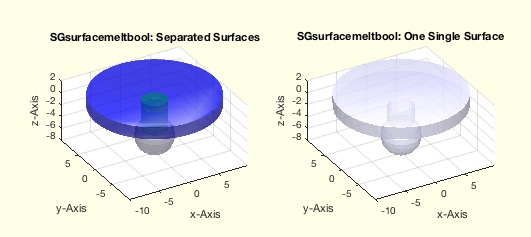 |
% SGsurfacemeltbool(SG,si,Amin,grw) - returns a solid which surfaces were added using SGbool % (by Tim Lueth, VLFL-Lib, 2017-AUG-08 as class: SURFACES) % % This fnctn is useful to melt overlapping solids into one solid by using % SGboolTL (Status of: 2017-08-16) % % Introduced first in SolidGeometry 4.1 % % See also: SGsurfaces, SGplotsurfaces, SGboolTL % % A=SGsurfacemeltbool(SG,[si,Amin,grw]) % === INPUT PARAMETERS === % SG: Original solid. All surfaces must overlap % si: indices of surfaces to melt; default is all; % Amin: Minimal Area removal; parameter for SGboolTL; default 0.01 % grw: Minimal grow factor; parameter for SGboolTL; default 1e-5 % === OUTPUT RESULTS ====== % A: Melted Object consisting of melted solids % % EXAMPLE: % A=SGsample(27); B=SGaddrelSG(SGsample(5),A,'incenter','ontop',-1); % SGsurfacemeltbool(B) % SGsurfacemeltbool(SGsample(17),[3,2,5,6]) % % % See also: SGsurfaces, SGplotsurfaces, SGboolTL % % % Copyright 2017 Tim C. Lueth |
SGbool5(flag,A,B,thr)- returns the correct result of a boolean operation on two closed elementary solids |
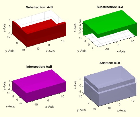 |
% SGbool5(flag,A,B,thr) - returns the correct result of a boolean operation on two closed elementary solids % (by Tim Lueth, VLFL-Lib, 2017-AUG-08 as class: SURFACES) % % SGbool5 hast much less limitations than SGbool3 and SGBool4. All fnctns % SGbool3-5 are now much faster. % Use CSGsample for testing. % Nevertheless, it should be clear that there are limitations even of % closed surface models with SGbool3 and SGBool4: % 1. Never have identical points in both surfaces % 2. Never have identical lines in both surfaces % 3. Never have indentical surface planes in both surfaces % If there is a risc, use SGgrow to grow before substraction or addition % by 1e-4 % It is possible to remove those problems one day by cutting tetrahedrons % instead of triangles % A => A without B % B => B without A % + => A combined with B % x => A intersected with B % % BTW: CATIA LIMITS THE SPATIAL RESOLUTION TO 0.01mm, ie. 1e-2 (Status % of: 2017-08-08) % % Introduced first in SolidGeometry 4.1 % % See also: SGbool, SGbool2, SGbool3, SGbool4 % % SGR=SGbool5(flag,A,B,[thr]) % === INPUT PARAMETERS === % flag: Boolean operator ('AB+x') % A: Solid A (VL/FL) % B: Solid B (VL/FL) % thr: threshold for grid; default is 1e-5 % === OUTPUT RESULTS ====== % SGR: resulting surface geometry % % EXAMPLE: % [A,B]=CSGsample(1); SGbool5('-',A,B); % [A,B]=CSGsample(2); SGbool5('-',A,B); % [A,B]=CSGsample(3); SGbool5('-',A,B); % [A,B]=CSGsample(4); SGbool5('-',A,B); % [A,B]=CSGsample(5); SGbool5('-',A,B); % [A,B]=CSGsample(6); SGbool5('-',A,B); % [A,B]=CSGsample(7); SGbool5('-',A,B); % % See also: SGbool, SGbool2, SGbool3, SGbool4 % % % Copyright 2017 Tim C. Lueth |
CSGsample(Nr,spatrel)- Cross-Pair Samples returns two solids as examples for crossing solids |
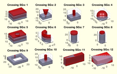 |
% CSGsample(Nr,spatrel) - Cross-Pair Samples returns two solids as examples for crossing solids % (by Tim Lueth, VLFL-Lib, 2017-AUG-06 as class: SURFACES) % % This is more or less an testing fnctn for SGbool and the supporting % fnctns: % SGintersectFacetPoints, VLFLinsertFacetPoints % The spatial relations are used from SGtransrelSG. % (Status of: 2018-07-28) % % Introduced first in SolidGeometry 4.1 % % See also: CPLsample, SGsample, VLsample, PLsample, VLFLsample, % SGerrorsample, testfunctTL, permutevector % % [A,B]=CSGsample([Nr,spatrel]) % === INPUT PARAMETERS === % Nr: Nr of Example % spatrel: spatial relations such as 'ontop',-15 % === OUTPUT RESULTS ====== % A: Solid A % B: Solid A % % EXAMPLE: % CSGsample % [A,B]=CSGsample(3,'ontop',-15); SGintersectFacetPoints(A,B); NPL=ans, % VLFLinsertFacetPoints(B.VL,B.FL,NPL(:,[2 1 3:end])); copyfig; % VLFLinsertFacetPoints(A.VL,A.FL,NPL); % % See also: CPLsample, SGsample, VLsample, PLsample, VLFLsample, % SGerrorsample, testfunctTL, permutevector % % % Copyright 2017-2018 Tim C. Lueth |
VLFLfaceNormalplot(VL,FL,c,t)- plots normal vector in appropriate length and writes the name of the facet at the tip |
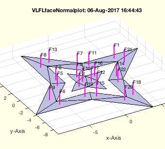 |
% VLFLfaceNormalplot(VL,FL,c,t) - plots normal vector in appropriate length and writes the name of the facet at the tip % (by Tim Lueth, VLFL-Lib, 2017-AUG-06 as class: VISUALIZATION) % % plots only the normal vectors in appropriate length and writes the name % of the facet at the tip. Use VLFLplot(VL,FL) to show the solid itself. % (Status of: 2017-08-06) % % Introduced first in SolidGeometry 4.1 % % See also: textT, textP, textVL, textCVL, textVLFL % % h=VLFLfaceNormalplot(VL,FL,[c,t]) % === INPUT PARAMETERS === % VL: Vertex list % FL: Facet List % c: Color, default is magenta % t: Thickness; default is 2 % === OUTPUT RESULTS ====== % h: handle to modify or delete text if necessary % % EXAMPLE: % [VL,FL]=VLFLsample(13); SGfigure; view(-30,30); VLFLplot(VL,FL); % VLFLfaceNormalplot(VL,FL); % % See also: textT, textP, textVL, textCVL, textVLFL % % % Copyright 2017 Tim C. Lueth |
SGrotate(SG,ax,val)- returns a solid rotated around the center of the solid |
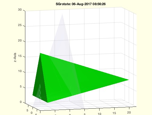 |
% SGrotate(SG,ax,val) - returns a solid rotated around the center of the solid % (by Tim Lueth, VLFL-Lib, 2017-AUG-06 as class: KINEMATICS AND FRAMES) % % Introduced first in SolidGeometry 4.1 % % See also: SGtransT, SGTrotate % % SGN=SGrotate(SG,[ax,val]) % === INPUT PARAMETERS === % SG: Solid Geoemtry % ax: rotation axis sequence; 'xyz' or 'x' or 'z' % val: values for rotation; same as ax % === OUTPUT RESULTS ====== % SGN: Spatial rotated Solid including the frames % % EXAMPLE: SGrotate(SGsample(18),'y',pi/2) % % See also: SGtransT, SGTrotate % % % Copyright 2017 Tim C. Lueth |
workdir (wd)- changes to the working directory and/or defines it |
 |
% workdir (wd) - changes to the working directory and/or defines it % (by Tim Lueth, VLFL-Lib, 2017-AUG-04 as class: AUXILIARY PROCEDURES) % % Introduced first in SolidGeometry 4.1 % % See also: desktopdir, pcodedirTL, smbFilename, smbPSLibname, expname % % workdir([wd]) % === INPUT PARAMETERS === % wd: working directory path % % See also: desktopdir, pcodedirTL, smbFilename, smbPSLibname, expname % % % Copyright 2017-2018 Tim C. Lueth |
iscalledbycmdline- returns wether a function was called by commandline directly |
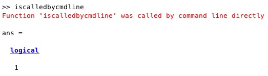 |
% iscalledbycmdline - returns wether a fnctn was called by commandline directly % (by Tim Lueth, VLFL-Lib, 2017-AUG-04 as class: AUXILIARY PROCEDURES) % % This is an auxiliary fnctn for developfnctns such as publishTL to % create help text in case that a fnctn is used not in a script or a % fnctn but in specific situations (Status of: 2017-08-04) % % Introduced first in SolidGeometry 4.1 % % See also: SGtitle % % b=iscalledbycmdline % === OUTPUT RESULTS ====== % b: logical true if length(dbstack) <=2 % % See also: SGtitle % % % Copyright 2017 Tim C. Lueth |