New in SG-Lib 3.4
PLoutercontour(CPL,out)- returns a point list that has no crossings |
 |
% PLoutercontour(CPL,out) - returns a point list that has no crossings % (by Tim Lueth and Jelena Prsa, VLFL-Lib, 2017-FEB-27 as class: CLOSED % POLYGON LISTS) % % In some cases, a fnctn such as CPLgrow creates cross that cross itself. % In this case, cw-oriented CPLs should return only the outer parts of % the contour and ccw-oriented CPLs should return the inner part of the % contour; The direction is detected automatically but can be overwritten % by the parameter out. Out=true => the outer contour is returned. % Out=false => the inner contour is returned. (Status of: 2017-02-28) % % See also: CPLoutercontour, CPLgrow % % [PLN,PLX]=PLoutercontour([CPL,out]) % === INPUT PARAMETERS === % CPL: Point List % out: returns the FIRST outer contour if true; if false the first inner; % default is true % === OUTPUT RESULTS ====== % PLN: Single Point List of the FIRST outer contour % PLX: Singe Point List of the FIRST outer contour % % EXAMPLE: % PLoutercontour(CPLgrow(CPLofPL(PLgearDIN(0.5,25)),-0.3),false); % |
TregisterConvexHull(VLA,VLB)- returns the registration matrix based on the convex hull of the vertices |
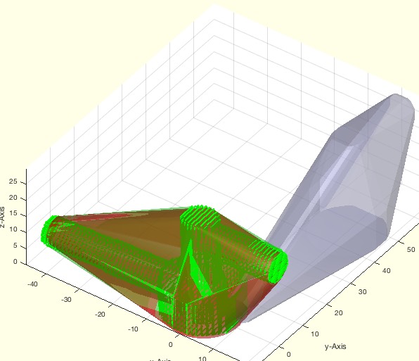 |
% TregisterConvexHull(VLA,VLB) - returns the registration matrix based on the convex hull of the vertices % (by Tim Lueth, VLFL-Lib, 2017-FEB-24 as class: ANALYTICAL GEOMETRY) % % This fnctn is just a simple fnctn for registering voxel models with % their original Solid Geoemtry (Status of: 2017-02-24) % % T=TregisterConvexHull(VLA,VLB) % === INPUT PARAMETERS === % VLA: Vertex list A or Solid A % VLB: Vertex list B or Solid B % === OUTPUT RESULTS ====== % T: Transformation from B into A % % EXAMPLE: Show the result of a random geoemtry % T=TofR(rot(pi/3,pi,6,pi/9,[10 10 10])), inv(T), VL=rand(10,3); % TregisterConvexHull(VL,VLtransT(VL,T)) % % |
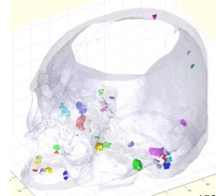
VMofSG(SG,n,adjxy,shsl)- returns a voxel model of a Solid Geoemtry |
 |
% VMofSG(SG,n,adjxy,shsl) - returns a voxel model of a Solid Geoemtry % (by Tim Lueth, VLFL-Lib, 2017-FEB-23 as class: VOXELS) % % The voxel size is adjusted automatically to maximize the resolution. % The absolute position in space is lost. The orientation is unchanged. % (Status of: 2017-02-27) % % See also: SGofVMdelaunay, SGofVMmarchcube, VMplot % % [VM,vs,SGN]=VMofSG([SG,n,adjxy,shsl]) % === INPUT PARAMETERS === % SG: Solid Geometry % n: Voxel size vector; default is [64 64 64] % adjxy: adjust x and y size; default is false % shsl: delay per slice if progress should be shown % === OUTPUT RESULTS ====== % VM: Voxel Model % vs: Voxel size % SGN: Optional Solid by marching cube % |
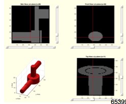
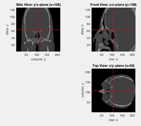
VMplot (IM,p,SG)- plots a 3D volumetric matrix in 2x2 view |
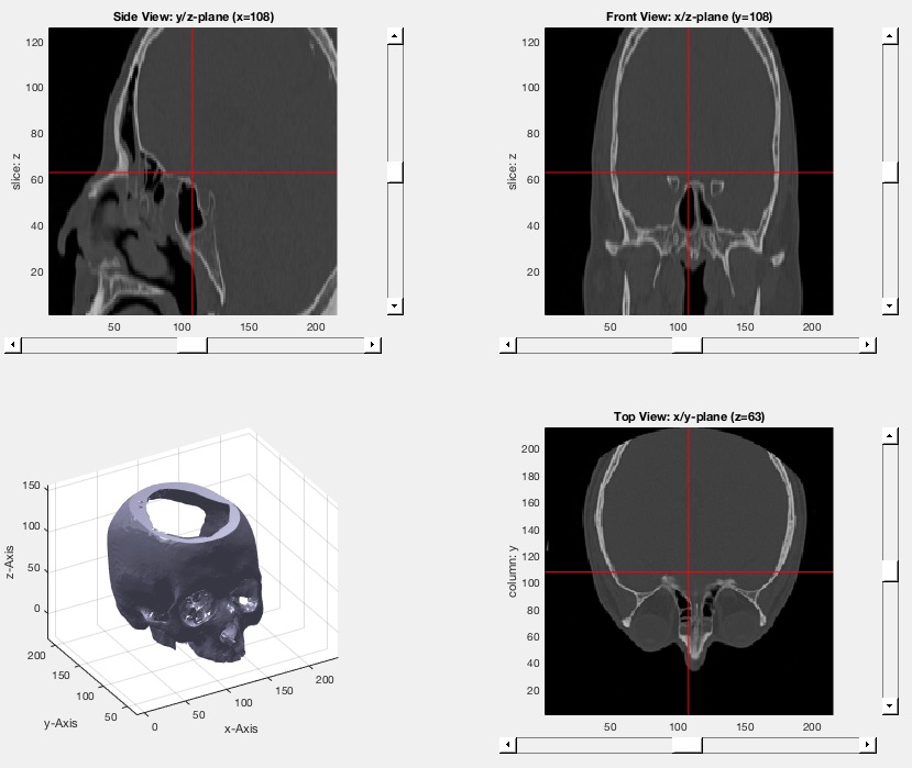 |
% VMplot (IM,p,SG) - plots a 3D volumetric matrix in 2x2 view % (by Tim Lueth, NAV-Lib, 2017-FEB-23 as class: VISUALIZATION) % % Based on VMplot_2012. Does support sliders for scrolling, and 3D % visualization; % % Global VMplotPos specifies the cross hair position % (Status of: 2017-04-02) % % See also: VMintensityscale, VMimage, VMimrot90, VMmontage, VMpseudo3D, % VMreaddicom, VMreaddicomdir, VMuidicom, VMgetSubplot, VMginput % % VMplot([IM,p,SG]) % === INPUT PARAMETERS === % IM: 3D Matrix % p: optional point of interest; default is center % SG: optional solid of the Volume; % % EXAMPLE: % [V,vs]=VMreaddicomdir('/Volumes/LUETH-WIN/WIN AIM Matlab % Libraries/VLFL-Lib/AIM_DICOMFILES'); % [V,vs]=VMresize(V,vs,vs); % SG=SGofVMdelaunay(V>1400,vs); % VMplot(V,'',SG) % % |
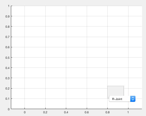
pixelofaxis- returns the axis position of the current axis in the figure |
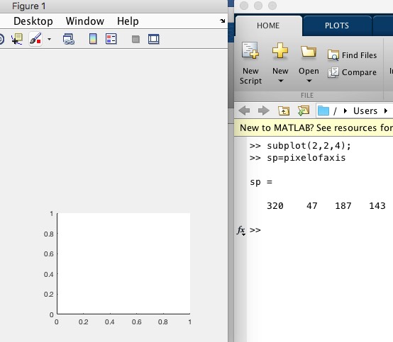 |
% pixelofaxis - returns the axis position of the current axis in the figure % (by Tim Lueth, VLFL-Lib, 2017-FEB-23 as class: USER INTERFACE) % % This fnctn is useful for placing uicontrol objects relative to subplots % such as in VMplot (Status of: 2017-02-24) % % See also: uipanel, uicontrol, pixelpositionofP, vertexpicker, select3d, % getpixelposition % % sp=pixelofaxis % === OUTPUT RESULTS ====== % sp: [left bottom size-x size-y] % % EXAMPLE: % subplot(2,2,4); % sp=pixelofaxis % uicontrol('Style', 'popup','String', % {'R-Joint','P-Joint','G-Joint'},'Position', sp) % |
SGsurfaceplot(SG,SIL,si)- plots the separated surfaces of SG in different colors |
 |
% SGsurfaceplot(SG,SIL,si) - plots the separated surfaces of SG in different colors % (by Tim Lueth, VLFL-Lib, 2017-FEB-22 as class: SURFACES) % % See also: SGfigure, SGplot, SGseparate, SGsurfaces, SGsurfacehistogram, % SGwriteSeparatedSTL, SGpuzzlecut3D % % [SG,SIL]=SGsurfaceplot(SG,[SIL,si]) % === INPUT PARAMETERS === % SG: Solid Geometry % SIL: Surface index list decending sorted by number of facets; % si: solid index for plot % === OUTPUT RESULTS ====== % SG: Solid Geometry % SIL: Surface Index List; created if missing % |
camset (p,d,ez)- sets the camera target to a specific point |
 |
% camset (p,d,ez) - sets the camera target to a specific point % (by Tim Lueth, VLFL-Lib, 2017-FEB-21 as class: USER INTERFACE) % % if no position is specified, the user will be requested to select a % point by a cross hair (Status of: 2017-02-21) % % See also: zoommpatch, camplot, tcamera % % camset([p,d,ez]) % === INPUT PARAMETERS === % p: point; default is ''; % d: diameter of axis % ez: direction to camera position; % % EXAMPLE: % camset ('',100); camplot; % |
camplot- plots a line of the current camera position |
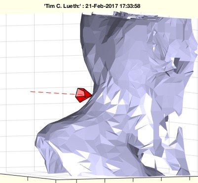 |
% camplot - plots a line of the current camera position % (by Tim Lueth, VLFL-Lib, 2017-FEB-21 as class: USER INTERFACE) % % See also: zoommpatch, camset, tcamera % % [p0,p1,v,a]=camplot % === OUTPUT RESULTS ====== % p0: CameraPosition % p1: CameraTarget % v: CameraViewAngle % a: axis % |
ROBgetJointPosition(KGID,jset)- returns the position of a set of joints of a robot |
 |
% ROBgetJointPosition(KGID,jset) - returns the position of a set of joints of a robot % (by Tim Lueth, RT-Lib, 2017-FEB-21 as class: KINEMATICS AND FRAMES) % % Procedure example for Samuel Detzel % The Kinematic Group ID is an identifier for a set of structural % connected joints such as a serial link robot arm % t0 = the time of the controller's internal clock when receiving the % ROBgetJointPosition command % t1 = the time of the controller's internal clock when sending the % ROBgetJointPosition results (Status of: 2017-02-22) % % [t,qi]=ROBgetJointPosition(KGID,[jset]) % === INPUT PARAMETERS === % KGID: Kinematic Group ID % jset: Joint set; defualt is empty == all joints of KGID % === OUTPUT RESULTS ====== % t: time vector (t0 t1) % qi: joint values of all or the requested set if joints [q1 q2 ] % |
exp_2017_02_21- EXPERIMENT SCRIPT to load and precalcuate a skull bone surface model |
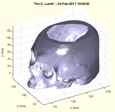 |
% exp_2017_02_21 - EXPERIMENT SCRIPT to load and precalcuate a skull bone surface model % (by Tim Lueth, VLFL-Lib, 2017-FEB-21 as class: EXPERIMENTS) % % exp_2017_02_21 % |
selectCameraPosition (p)- selects and sets the camera position |
 |
% selectCameraPosition (p) - selects and sets the camera position % (by Tim Lueth, VLFL-Lib, 2017-FEB-21 as class: USER INTERFACE) % % selectCameraPosition([p]) % === INPUT PARAMETERS === % p: point to set; default is empty % |
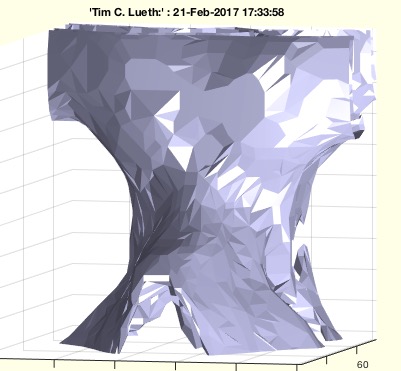
SGofVMdelaunay(V,vs,s)- returns a surface model for a delaunay reconstructed volume model |
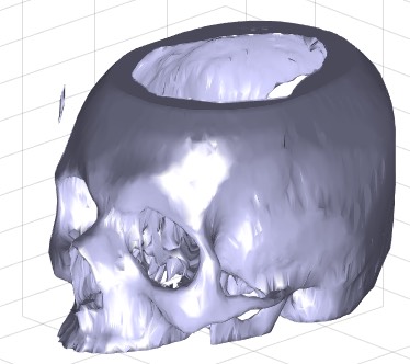 |
% SGofVMdelaunay(V,vs,s) - returns a surface model for a delaunay reconstructed volume model % (by Tim Lueth, VLFL-Lib, 2017-FEB-17 as class: VOXELS) % % This fnctn takes about 20 second for a 256 x 256 x 100 voxel model. % (Status of: 2017-02-18) % % See also: VLFLofVMdelaunay, VLFLofVMmarchcube, TR3ofVM, SGofVMmarchcube % % [SG,TR4]=SGofVMdelaunay(V,[vs,s]) % === INPUT PARAMETERS === % V: Voxel Model (~=0 is reconstruction) % vs: voxel size, optional % s: step size % === OUTPUT RESULTS ====== % SG: Solid Geoemtry % TR4: Delaunay tetrahedron model % % EXAMPLE: % [V,vs]=VMreaddicomdir('AIM_DICOMFILES'); % [a,as]=VMresize(V,[0.5 0.5 0.5],vs); % SG=SGofVMdelaunay(a>1400,as); % SGcut(SG,40); % c=CPLofSGslice3(SG,20); % PLFLofCPLdelaunay(c); % PLFLofCPLpoly(c) % |
SGofVMmarchcube(V,vs,cl)- returns a surface model by the marching cubes |
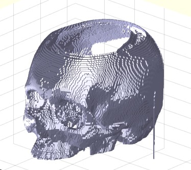 |
% SGofVMmarchcube(V,vs,cl) - returns a surface model by the marching cubes % (by Tim Lueth, VLFL-Lib, 2017-FEB-17 as class: VOXELS) % % This fnctn uses the MarchingCubes fnctn from Matlab Central written by % Peter Hammer in 2011 based on the Octave fnctn written by Martin Helm % (www.mhelm.de/octave/m/marching_cube.m) in 2009. It contains also code % from Oliver Woodford for removing duplicated vertices. (Status of: % 2017-02-23) % % See also: VLFLofVMdelaunay, VLFLofVMmarchcube, TR3ofVM, SGofVMdelaunay % % SG=SGofVMmarchcube(V,[vs,cl]) % === INPUT PARAMETERS === % V: Logical Volume Model % vs: voxel size, optional % cl: closes open facets by adding empty planes; default is true % === OUTPUT RESULTS ====== % SG: Vertex list % % EXAMPLE: [V,vs]=VMreaddicomdir('AIM_DICOMFILES'); % [a,as]=VMresize(V,[0.5 0.5 0.5],vs); % SG=SGofVMmarchcube(a>1400,as); % SGcut(SG,40); % c=CPLofSGslice3(SG,20); % PLFLofCPLdelaunay(c); % PLFLofCPLpoly(c) % |
VMresize(VM,dm,vs)- resizes a voxel image model |
 |
% VMresize(VM,dm,vs) - resizes a voxel image model % (by Tim Lueth, VLFL-Lib, 2017-FEB-17 as class: VOXELS) % % [V,vs]=[V,vs,vs]); returns voxels of same size 1 mm x 1mm x 1mm % [V,vs]=[V,vs); returns voxels of same size 1 mm x 1mm x 1mm % (Status of: 2017-02-17) % % See also: VMreaddicomdir, VMmontage, VMplot, VMintensityscale % % [FVM,vs]=VMresize(VM,[dm,vs]) % === INPUT PARAMETERS === % VM: voxel mode; [X x Y x Z] % dm: dimension either scale [0.5 0.5 0.5] or vs % vs: optional voxel size for rescaling; default is dm % === OUTPUT RESULTS ====== % FVM: New Voxel Model with new dimensions % vs: Voxel size after resizing % % EXAMPLE: % [V,vs]=VMreaddicomdir('AIM_DICOMFILES'); % VMresize(V,vs,vs); % voxel size = 1 mm % VMresize(V,vs/2,vs); % voxel size = 2 mm % |
SGgethandle(SG)- returns a handle if the object is already drawn in gca |
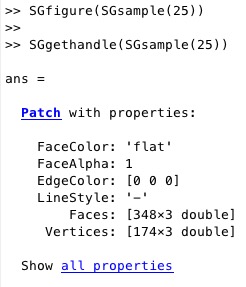 |
% SGgethandle(SG) - returns a handle if the object is already drawn in gca % (by Tim Lueth, VLFL-Lib, 2017-FEB-14 as class: USER INTERFACE) % % Does not support all kinds of SG yet. % Is more a VLFLgethandle fnctn (Status of: 2017-02-14) % % See also: SGplot % % h=SGgethandle(SG) % === INPUT PARAMETERS === % SG: Solid Geometry % === OUTPUT RESULTS ====== % h: handle % |
selectV3d(SG)- plots a SG in a figure and shows selected normal vectors of a selected corner |
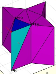 |
% selectV3d(SG) - plots a SG in a figure and shows selected normal vectors of a selected corner % (by Tim Lueth, VLFL-Lib, 2017-FEB-14 as class: USER INTERFACE) % % See also: select3d, vertexpicker % % selectV3d([SG]) % === INPUT PARAMETERS === % SG: Solid Geometry to plot % |
FLselect(FL,vi)- returns all neighbor facets of vi |
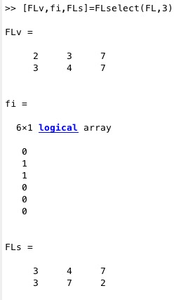 |
% FLselect(FL,vi) - returns all neighbor facets of vi % (by Tim Lueth, VLFL-Lib, 2017-FEB-14 as class: AUXILIARY PROCEDURES) % % Some fnctns such as MLofSG process a complete solid. Nevertheless, % finally, only facets that are linked to a vertex are required. FLselect % returns form a FL the index of all facts that contain vi, the reduced % facet list, and a facet list that is sorted in a way that the FL starts % always with vi % (Status of: 2017-02-14) % % [FLv,fi,FLs]=FLselect(FL,vi) % === INPUT PARAMETERS === % FL: Facet list % vi: index of vertex % === OUTPUT RESULTS ====== % FLv: reduced facet list % fi: facet index of FL % FLs: FL with sortet rows % % EXAMPLE: % [VL,FL]=VLFLcone(30,'',6) % [FLv,fi,FLs]=FLselect(FL,3) % |
VLbreakEdges(VL,R)- returns a vertex list (VL) with broken edges |
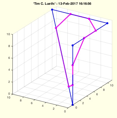 |
% VLbreakEdges(VL,R) - returns a vertex list (VL) with broken edges % (by Tim Lueth, VLFL-Lib, 2017-FEB-13 as class: ANALYZING PROCEDURES) % % Replaces edges by a simple shortcut. The desired radius can be reduced % automatically if necessary. It is possible to maximize the radius % automatically. % In case that R is negative; VLradialEdges is used instead (Status of: % 2017-02-13) % % See also: PLradialEdges, SGcontourtube, RLofEulerInterpolation, % VLinsertEulerSteps, VLradialEdges, TofPez, PLtangentcirc, % VLtangentcirc, SGbreakCorners, SGradialCorners % % NVL=VLbreakEdges(VL,[R]) % === INPUT PARAMETERS === % VL: Vertex list nx3 % R: Radius; default is 1 % === OUTPUT RESULTS ====== % NVL: New vertex list % % EXAMPLE: % VL=roundn(rand(6,3)*100,5) % VLbreakEdges(VL,2) % VLbreakEdges([0 0 0;0 0 100; 100 0 100;100 100 100]); view(0,0) % VLbreakEdges([0 0 0;0 0 100; 100 0 0],10); view(0,0) % |
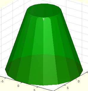
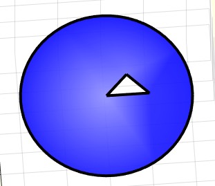
SGcone(H,R,nf)- returns a solid geometry of a cone |
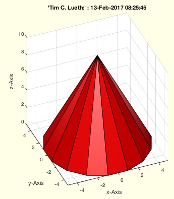 |
% SGcone(H,R,nf) - returns a solid geometry of a cone % (by Tim Lueth, VLFL-Lib, 2017-FEB-13 as class: MODELING PROCEDURES) % % uses VLFLcone; (Status of: 2017-02-13) % % See also: VLFLcone, SGsphere, SGbox, SGlinkage, SGtext % % [SG,FL,FLb]=SGcone(H,[R,nf]) % === INPUT PARAMETERS === % H: Height % R: Radius; default is H/2 % nf: Number of facets, default is 16 % === OUTPUT RESULTS ====== % SG: Vertex list % FL: Facet list of the cone % FLb: Facet list of the bottom % |
exp_2017_02_13 (A,vi,R)- Experiment for analyzing normal vectors of facets and corners and edges |
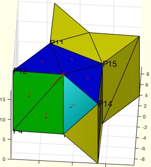 |
% exp_2017_02_13 (A,vi,R) - Experiment for analyzing normal vectors of facets and corners and edges % (by Tim Lueth, VLFL-Lib, 2017-FEB-13 as class: EXPERIMENTS) % % Around mid Feb, im getting tired to reimplement CAD fnctns that I just % need to convince students/researcher that are used to use CATIA instead % of improving design processes (Status of: 2017-02-14) % % exp_2017_02_13([A,vi,R]) % === INPUT PARAMETERS === % A: Solid Geoemtry % vi: vertex of interest (corner); 0 == select graphically % R: Optional Radius % |
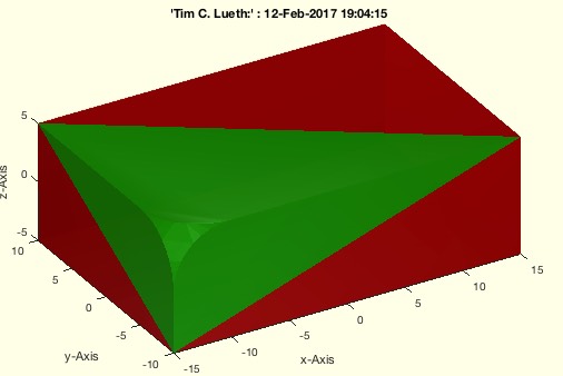
FLofDelaunay(VL,vni)- returns the convex hull of a vertex list |
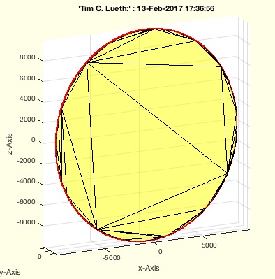 |
% FLofDelaunay(VL,vni) - returns the convex hull of a vertex list % (by Tim Lueth, VLFL-Lib, 2017-FEB-12 as class: SURFACES) % % works with 2D and 3D and plane surfaces in 3D % By intention, matlab's delaunayTriangulation does not return a % tesselation for 3D coordinates if all vertices are in one plane since % in 3D the fnctns returns a tetrahedron tesselation. In this case, a % transformation matrix is calculated from the vertex list, the vertex % list is transformed into a point list, and a 2D tesselation is % returned. SOMETIMES, delaunayTriangulation, returns also a tesselation % for planar structures. THis has to be detected in future (Status of: % 2017-02-12) % % FL=FLofDelaunay(VL,[vni]) % === INPUT PARAMETERS === % VL: Vertex list (nx2) or (nx3) % vni: optional index of VL % === OUTPUT RESULTS ====== % FL: Facet list to close VL(vni,:) % % EXAMPLE: % FLofDelaunay(VLtransR(VLaddz(PLstar(10,30),30),rot(pi/3,pi/3,pi/3))) % FLofDelaunay(rand(100,3)*100-50) % |
SGradialCorners(A,vi,R)- should breaks corners and edges of solids |
 |
% SGradialCorners(A,vi,R) - should breaks corners and edges of solids % (by Tim Lueth, VLFL-Lib, 2017-FEB-12 as class: SURFACES) % % If vi==0, the user should select interactively a vertex % First all patches/plane surfaces connected to an corner are calculated. % For the further calculation only the vertices are used that define the % outer limits of the face. This fnctn uses VLradialEdges to replace the % original edges at a corned by a corved convex element. Completely new % version on 2017-20-12 based on exp_2017_02_12. % (Status of: 2017-02-13) % % See also: SGbreakCorners, VLradialEdges % % A=SGradialCorners([A,vi,R]) % === INPUT PARAMETERS === % A: Solid Geometry % vi: list of corned index (n) or corner vertex list (nx3); default is '' % R: radius; default is 1mm % === OUTPUT RESULTS ====== % A: Solid Geometry with rounded corners % |
findVL(NVL,VL,ai,thr)- returns the indices of a list in another list |
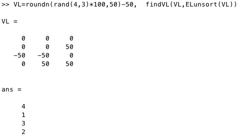 |
% findVL(NVL,VL,ai,thr) - returns the indices of a list in another list % (by Tim Lueth, VLFL-Lib, 2017-FEB-12 as class: AUXILIARY PROCEDURES) % % This fnctn finds the indices of some vertices in a longer list. For a % complete remapping use fnctn "maprows". % bi=findVL(VL,ai); bi=ai(bi) (Status of: 2017-02-13) % % See also: maprows, reversesortindex % % bi=findVL(NVL,VL,[ai,thr]) % === INPUT PARAMETERS === % NVL: Long vertex list to search in % VL: Second vertex list to find in NVL % ai: optional index list to search for % thr: threshold for find; default is 1e-12 % === OUTPUT RESULTS ====== % bi: index in NVL % % EXAMPLE: % VL=roundn(rand(20,3)*100,5)-50 % findVL(VL,unique(VL,'rows')) % |
exp_2017_02_12(A,vi,R)- Experiment to show the breaking of vertices |
 |
% exp_2017_02_12(A,vi,R) - Experiment to show the breaking of vertices % (by Tim Lueth, VLFL-Lib, 2017-FEB-12 as class: EXPERIMENTS) % % First all patches/plane surfaces connected to an corner are calculated. % For the further calculation only the vertices are used that define the % outer limits of the surface. % This fnctn uses VLradialEdges to replace the original edges at a corned % by a corved convex element. (Status of: 2017-02-12) % % See also: SGbreakvertices, SGradialCorners, exp_2017_02_01 % % A=exp_2017_02_12([A,vi,R]) % === INPUT PARAMETERS === % A: Solid Geoemtry % vi: list of corned index (n) or corner vertex list (nx3); default is 4 % R: radius; default is 1mm % === OUTPUT RESULTS ====== % A: Solid Geoemtry with rounded corners % |
Tof2vec(p1,p2,q1,q2)- returns transformation matrix based on the 2 point movements |
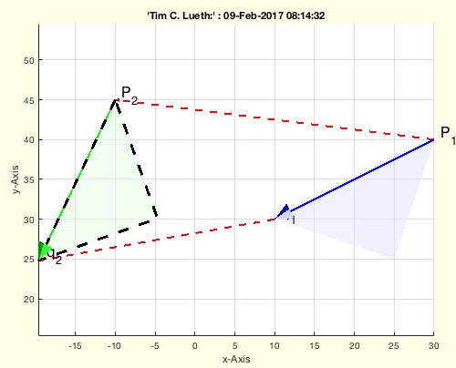 |
% Tof2vec(p1,p2,q1,q2) - returns transformation matrix based on the 2 point movements % (by Tim Lueth, VLFL-Lib, 2017-FEB-08 as class: ANALYTICAL GEOMETRY) % % This fnctn helps to transform points from one coordinate system into % another based on two known point movements. P1 is the center of the 1st % and P2 is the center of the second system. % W_T_P1 and W_T_P2 ==> P2_T_P1 ==> P2_T_P1 * P1_P (Status of: % 2017-02-09) % % See also: TofR, TofVL, TPL, TofDPhiH, T3ofT2, T3P, T2P, TofP, TofPez, % TofPEul % % [T12,T21]=Tof2vec(p1,p2,q1,q2) % === INPUT PARAMETERS === % p1: 1st point before movement % p2: 1st point after movement % q1: 2nd point before movement % q2: 2nd point before movement % === OUTPUT RESULTS ====== % T12: 2_T_1 Transformation from T1 into T2 % T21: 1_T_2 Transformation from T2 into T1 % % EXAMPLE: % Tof2vec([0 10],[-10 10],[0 15],[-20 10]) % |
CPLfaceplot(PL,c,w,a)- plots the faces of a CPL |
 |
% CPLfaceplot(PL,c,w,a) - plots the faces of a CPL % (by Tim Lueth, VLFL-Lib, 2017-FEB-08 as class: CLOSED POLYGON LISTS) % % See also: VLELplots, CPLplot, PLplot, VLplot % % h=CPLfaceplot(PL,[c,w,a]) % === INPUT PARAMETERS === % PL: Point List or CPL % c: color % w: countour width % a: alpha; default is 0.5 % === OUTPUT RESULTS ====== % h: handle % % EXAMPLE: % SGfigure; % CPLfaceplot([PLcircle(20);NaN NaN; [0 0; 10 0; 5 5]],'b',0.1) % |
textP(p,str,delx,dely,Fnts)- draws a texlabel text at the position |
 |
% textP(p,str,delx,dely,Fnts) - draws a texlabel text at the position % (by Tim Lueth, VLFL-Lib, 2017-FEB-07 as class: ANALYTICAL GEOMETRY) % % See also: textT, textVL, textCVL % % h=textP(p,str,[delx,dely,Fnts]) % === INPUT PARAMETERS === % p: point % str: texlabel % delx: displacement x; default is 0.02 (2%) % dely: displacement y; default is 0.02 (2%) % Fnts: Fontsize; default is 16 % === OUTPUT RESULTS ====== % h: handle to text % |
exp_2017_02_07- |
 |
% exp_2017_02_07 - % (by Tim Lueth, VLFL-Lib, 2017-FEB-07 as class: ANALYTICAL GEOMETRY) % % exp_2017_02_07 % |
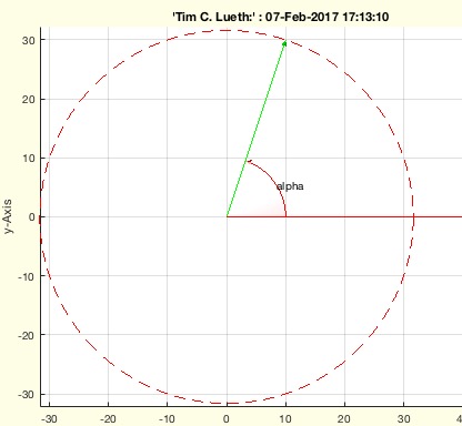
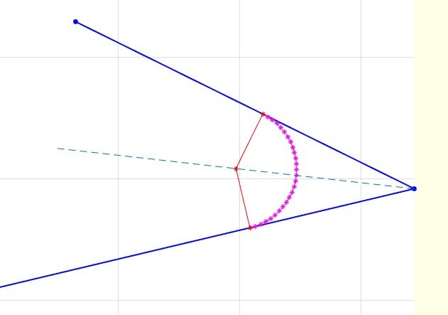
aplot(pc,la,lb,c,w,r,alpha)- draws an angle relative to a center and two vectors |
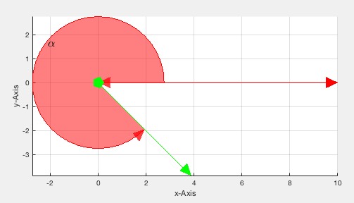 |
% aplot(pc,la,lb,c,w,r,alpha) - draws an angle relative to a center and two vectors % (by Tim Lueth, VLFL-Lib, 2017-FEB-07 as class: ANALYTICAL GEOMETRY) % % See also: aplot, pplot, lplot, tfplot, tlplot, slplot, plotTP, plotL, % plotT, T2Plot, textP, textT, textVL % % [h,pt,a]=aplot(pc,la,[lb,c,w,r,alpha]) % === INPUT PARAMETERS === % pc: center of angle % la: 1st vector % lb: 2nd vector or angle or rotation matrix % c: color; default is 'r' % w: width of lines; default is 1; % r: radius; default is % alpha: transparency % === OUTPUT RESULTS ====== % h: handle to all elements of the angle drawing % pt: point for text desciption % a: angle that was used if lb was a vector % % EXAMPLE: % [h,pt]=aplot ([0 0],[10 0],3.5*pi/2) % textP(pt,'alpha'); % |
pixelpositionofP(p)- returns the pixelposition of a point coordinate |
 |
% pixelpositionofP(p) - returns the pixelposition of a point coordinate % (by Tim Lueth, VLFL-Lib, 2017-FEB-06 as class: USER INTERFACE) % % If uipanels or uicontrols should be placed at point coordinates, the % position of a point coordinate relative to the figure is requested. % It does not work correctly yet for axis equal; % Panels are moved correctly, but not fixed pixel positions (Status of: % 2017-03-19) % % See also: uipanel, uicontrol, vertexpicker, select3d, getpixelposition, % pixelofaxis % % [pf,ppf,ppa]=pixelpositionofP(p) % === INPUT PARAMETERS === % p: point coordinate [x y] % === OUTPUT RESULTS ====== % pf: pixel coordinate in figure (uicontrol) % ppf: pixel coordinate in percentage of figure (uipanel) % ppa: pixel coordinate in percentage of axis % % EXAMPLE: set a uipanel at 0.8 0.1 % figure; axis on; grid on; axis equal % pixelpositionofP([0.8 0.1]) % % |
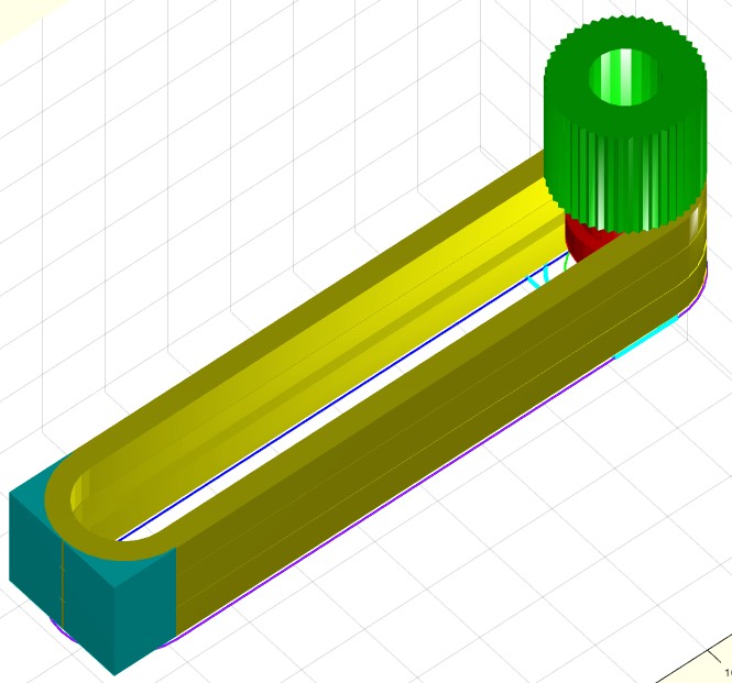
SGmodelLink4(L,L1,L2,K,H)- Creates Solid for a Link im Style "Link4" |
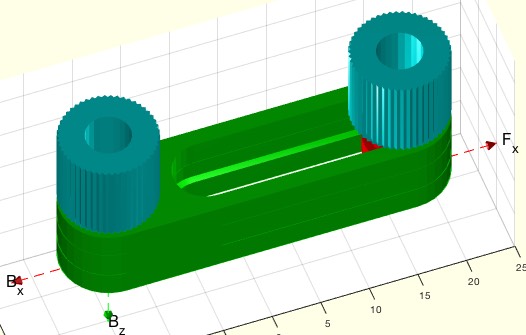 |
% SGmodelLink4(L,L1,L2,K,H) - Creates Solid for a Link im Style "Link4" % (by Tim Lueth, VLFL-Lib, 2017-FEB-05 as class: MODELING PROCEDURES) % % Notation style % 0= same level % +n = n* Height H above z plane % -n = n* height H under z plane % Knob Position % 'BU' = Base frame upper side % 'BL' = Base frame lower sider % 'BU' = Follower Frame upper side % 'BL' = Follower Frame lower sider (Status of: 2017-02-05) % % See also: SGmodelLink, SGmodelJoint, SGmodelNode, SGmodelLink3, % SGmodelKeyhole, SGmodelLink1, SGmodelLink2, SGmodelLink3 % % [SG,SGA,SGB]=SGmodelLink4([L,L1,L2,K,H]) % === INPUT PARAMETERS === % L: Length % L1: Level of Frame B; default is 0 % L2: Level of Frame F; default is 1 % K: Knob position; default is '' % H: Height of link; default is 9 % === OUTPUT RESULTS ====== % SG: Solid Geoemtry including Frames % SGA: Left joint of the link % SGB: Right joint of the link % % EXAMPLE: % A=SGmodelLink4('',0,2);SGaddrelSG(A,A,'alignT',{'B','F'}); % A=SGmodelLink4('',0,1);SGaddrelSG(A,A,'alignT',{'B','F'}); % A=SGmodelLink4('',0,-1,'BL,FU');SGaddrelSG(A,A,'alignT',{'B','F'}); % % |
SGmodelSliderhole(RA,RO,lw,LA,LO,HO,slot,WI)- Creates a SG including a key and a keyhole |
 |
% SGmodelSliderhole(RA,RO,lw,LA,LO,HO,slot,WI) - Creates a SG including a key and a keyhole % (by Tim Lueth, VLFL-Lib, 2017-FEB-05 as class: MODELING PROCEDURES) % % SG modeling fnctn to create revolute joint that can be printed % assembled or separated and can be lined on an axis (Status of: % 2017-02-05) % % See also: SGmodelLink, SGmodelJoint, SGmodelNode, SGmodelLink3, % SGmodelKeyhole, SGmodelLink1, SGmodelLink2 % % [SGK,SGH,SGP,SGT,SGB]=SGmodelSliderhole([RA,RO,lw,LA,LO,HO,slot,WI]) % === INPUT PARAMETERS === % RA: Axle Radius % RO: Outer Radius % lw: Length of sliding distance % LA: [L1 L2 L3] describing key length % LO: [L1 L2 L3] describing key hole length % HO: Width of a flange in distance RO; default is 2*RO % slot: default is 0.3 mm (SLS & SLA) % WI: Inner Wall Thickness % === OUTPUT RESULTS ====== % SGK: Solid Geoemtry of Key % SGH: Solid Geoemtry of Keyhole % SGP: Solid Geometry of flange plate % SGT: Optional Knob on the upper side; separated from SGK % SGB: Optional Knob on the lower side; separated from SGK % % EXAMPLE: Print job was successful on Form2 SLA-Printer on 2017-02-05 % SGmodelSliderhole(3,6,'',9) % [A,B,C,D]=SGmodelSliderhole(3,6,'',9); % SGanalyzeGroupParts({A,B,C,D}) % % |
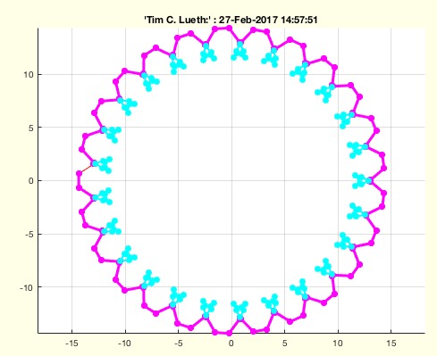
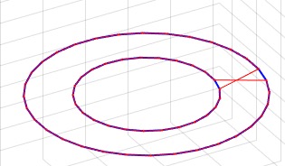
PLcircleoval(R,n,L,Ri)- returns a circle-based-oval point-list |
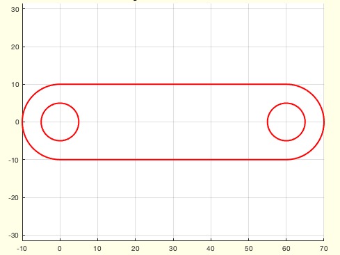 |
% PLcircleoval(R,n,L,Ri) - returns a circle-based-oval point-list % (by Tim Lueth, VLFL-Lib, 2017-FEB-05 as class: ANALYTICAL GEOMETRY) % % Introduced first in SolidGeometry 3.4 % % See also: PLcircle, PLcircseg, PLevolvente, PLgearDIN, PLhelix, % PLkidney, PLrand, PLspiral, PLsquare, PLstar % % PL=PLcircleoval([R,n,L,Ri]) % === INPUT PARAMETERS === % R: Radius % n: optional number of points for half circle % L: Length; default is 0; % Ri: optional inner Radius for links; default is 0 % === OUTPUT RESULTS ====== % PL: Point List % % EXAMPLE: % SGfigure; CPLplot(PLcircleoval(10,'',60,5),'r-',2) % % See also: PLcircle, PLcircseg, PLevolvente, PLgearDIN, PLhelix, % PLkidney, PLrand, PLspiral, PLsquare, PLstar % |
PLofCPL(CPL)- converts a nested CPL into a nested PL |
 |
% PLofCPL(CPL) - converts a nested CPL into a nested PL % (by Tim Lueth, VLFL-Lib, 2017-FEB-01 as class: CLOSED POLYGON LISTS) % % This fnctn is useful if CPLS are extruded to solids. CPLs are contours % that are separted by NaN NaN. Nevertheless; sometimes the first point % is doubled at the end, somethimes not. This fnctn returns CPLs that are % separated by NaN NaN but the point lists are open % Works with PL and VL (Status of: 2017-02-03) % % See also: CPLofPL % % NPL=PLofCPL(CPL) % === INPUT PARAMETERS === % CPL: Closed polygon list with unclear closing condition % === OUTPUT RESULTS ====== % NPL: Closed polygon list with open polygons % % EXAMPLE: Try % PLofCPL([PLcircle(5);NaN NaN;PLcircle(3)]) % There are no changes % PLofCPL(CPLsample(7)) % remove the closing lines % PLofCPL(VLaddz(CPLsample(7))) % Now try with VL % |
centerPL(PL)- returns the mean of the convex hull of the point list |
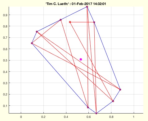 |
% centerPL(PL) - returns the mean of the convex hull of the point list % (by Tim Lueth, VLFL-Lib, 2017-FEB-01 as class: ANALYTICAL GEOMETRY) % % See also: center3P, center4P, centerVL % % pc=centerPL(PL) % === INPUT PARAMETERS === % PL: Point list (n x 2) % === OUTPUT RESULTS ====== % pc: point list center % % EXAMPLE: try: % centerPL(rand(10,2)) % |
exp_2017_02_01- Experiment to show the breaking of vertices |
 |
% exp_2017_02_01 - Experiment to show the breaking of vertices % (by Tim Lueth, VLFL-Lib, 2017-FEB-01 as class: EXPERIMENTS) % % This fnctn uses VLradialEdges to replace the original edges at a corned % by a corved convex element. % There is still a problem if more than one point is linked to the corner % for the same plane surface (Status of: 2017-02-03) % % See also: SGbreakvertices, SGradialCorners % % exp_2017_02_01 % |
woNaN(PL)- returns a row list without all rows that have a NaN in first row |
 |
% woNaN(PL) - returns a row list without all rows that have a NaN in first row % (by Tim Lueth, VLFL-Lib, 2017-FEB-01 as class: AUXILIARY PROCEDURES) % % For the construction of planar or spacial contours the concept of NaN % separated polygons was introduced in the mapping toolbox. Nevertheless % when changing to triangulation representation (delaunaytriangulation or % triangulation) those NaN are a problem. Either use VLFLselect in case % that faces exist already or use woNaN to remove the NaN (Status of: % 2017-02-02) % % See also: PLofCPL, VLFLselect, VLELselect % % PL=woNaN(PL) % === INPUT PARAMETERS === % PL: vector row list containing NaN % === OUTPUT RESULTS ====== % PL: vector row list without NaN % % EXAMPLE: Shows the effect for closed polygon lines % PL=PLofCPL([PLcircle(5);NaN NaN;PLcircle(3)]) % CPLplot(PL) % CPLplot(woNaN(PL)) % |
VLtangentcirc(v1,v2,R,M)- creates a vertex list for a tangential circle segment |
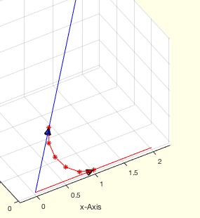 |
% VLtangentcirc(v1,v2,R,M) - creates a vertex list for a tangential circle segment % (by Tim Lueth, VLFL-Lib, 2017-FEB-01 as class: ANALYTICAL GEOMETRY) % % This fnctn is used in VLradialedges (Status of: 2017-02-01) % % See also: VLradialEdges, PLtangentcirc % % VL=VLtangentcirc([v1,v2,R,M]) % === INPUT PARAMETERS === % v1: vector 1 from the origin % v2: vector 2 from the origin % R: desired Radius; automatically reduced; default is 1 % M: maximize radius if possible; default is false % === OUTPUT RESULTS ====== % VL: Vertex list describing a circle segment % % EXAMPLE: Try different parameters % VLtangentcirc % VLtangentcirc([5 0 0],[5 5 5],0.5) % VLtangentcirc([5 0 0],[5 5 5],0.5,true) % |
FLwallofCPL(CPL,z)- returns only the wall and the cover wrt a CPL |
 |
% FLwallofCPL(CPL,z) - returns only the wall and the cover wrt a CPL % (by Tim Lueth, VLFL-Lib, 2017-FEB-01 as class: SURFACES) % % In contrast to VLFLof CPLz, this fnctn returns only the faces of the % wall between two nested CPLs % % WORK IN PROGRESS (Status of: 2017-02-03) % % [FLW,FLT,CPL,VL]=FLwallofCPL(CPL,[z]) % === INPUT PARAMETERS === % CPL: Closed Polygon List % z: optional z value % === OUTPUT RESULTS ====== % FLW: Facets of the Wall % FLT: Facets of the Top % CPL: Corrected Closed Polygon Line (nested but open) % VL: Vertex list % |
PLtangentcirc(p1,p2,p3,R,M)- returns the a circ segment between p1 and p3 with radius R |
 |
% PLtangentcirc(p1,p2,p3,R,M) - returns the a circ segment between p1 and p3 with radius R % (by Tim Lueth, VLFL-Lib, 2017-JAN-31 as class: ANALYTICAL GEOMETRY) % % See also: VLradialEdges, VLtangentcirc % % [PLS,pc]=PLtangentcirc([p1,p2,p3,R,M]) % === INPUT PARAMETERS === % p1: 1st point; alternatively PL % p2: 2nd point; alternatively desired radius % p3: 3rd point;; alternatively maximize radius; % R: Desired Radius % M: maximize radius; default is false % === OUTPUT RESULTS ====== % PLS: Point List to replace 2nd point of the list % pc: % % EXAMPLE: try different examples % PLtangentcirc (CPLsample(1),5); % |
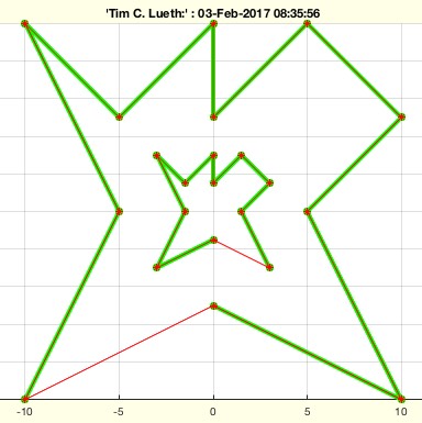
VLsample(Nr,T)- returns a sample vertex list for testing algorithms |
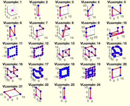 |
% VLsample(Nr,T) - returns a sample vertex list for testing algorithms % (by Tim Lueth, VLFL-Lib, 2017-JAN-31 as class: MODELING PROCEDURES) % % See also: CPLsample, SGsample, PLsample % % [VL,PL]=VLsample([Nr,T]) % === INPUT PARAMETERS === % Nr: Nr of sample solid; default is none % T: Parameter for VLtrans (Value, Vector, Matrix) % === OUTPUT RESULTS ====== % VL: Solid geometry % PL: Point list % |