New in SG-Lib 3.1
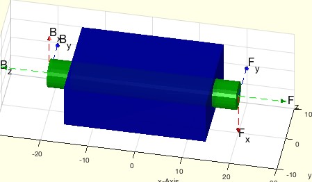
smbFullModelSimulation(t)- returns a SG configuration at a given time |
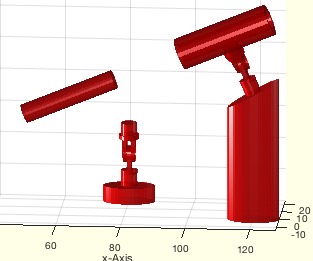 |
% smbFullModelSimulation(t) - returns a SG configuration at a given time % (by Tim Lueth, SimMechanics, 2016-DEZ-19 as class: VISUALIZATION) % % WORK in PROGRESS: It is still unclear, why the procedure aborts so % often during smbAddFrameSensor. It seems that there is no % synchronisation when creating blocks and lines and subsystems. % % The procedure analyzeses the current system bdroot and creates a list % of solids. Afterwards the procedure adds frames sensors for each % reference frame of the solid. Next, the SimMultiBody model is % simulation until recording all solid-frames until the specified point % of time is reached. Either the first or the last time is used to create % a solid. Nevertheless, by using more than one output parameter, also % other time frames can be used. (Status of: 2016-12-20) % % See also: smbAddFrameSensor, smbSimulate % % [SG,BNi,SGi,Ti,tm]=smbFullModelSimulation(t) % === INPUT PARAMETERS === % t: Optional time value; default is 0 % === OUTPUT RESULTS ====== % SG: Compiled SG at the specific given time % BNi: Names of the used solid geometries % SGi: Solid geometries % Ti: T matrixes of the solids over time % tm: list of time values % |
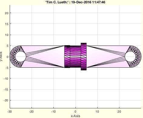
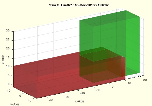
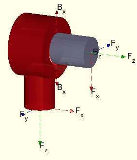
SGof2SGT(A,FA,T1,B,FB,T2,Rv,NCPL)- Creates a solid between two solids with frames |
 |
% SGof2SGT(A,FA,T1,B,FB,T2,Rv,NCPL) - Creates a solid between two solids with frames % (by Tim Lueth, VLFL-Lib, 2016-DEZ-19 as class: MODELING PROCEDURES) % % See also: SGof2T, SGof2CVL, SGof2CPLz % % SG=SGof2SGT(A,FA,T1,B,FB,T2,[Rv,NCPL]) % === INPUT PARAMETERS === % A: Solid A % FA: Framename of A % T1: Current position in Space of Frame a % B: Solid A % FB: Framename of A % T2: Current position in Space of Frame a % Rv: Optional Radius for Solid % NCPL: Optional Contour for Radius % === OUTPUT RESULTS ====== % SG: Solid Geoemtry % |
VLFL_EXP23- Experiment for SimMultiBody 2016b |
 |
% VLFL_EXP23 - Experiment for SimMultiBody 2016b % (by Tim Lueth, EXPERIMENT, 2016-DEZ-19 as class: EXPERIMENTS) % % VLFL_EXP23 % |
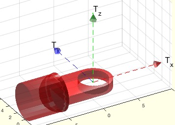
SGreadSTL(FName,mag)- reads in an SG from an STL File |
 |
% SGreadSTL(FName,mag) - reads in an SG from an STL File % (by Tim Lueth, VLFL-Lib, 2016-DEZ-18 as class: FILE HANDLING) % % See also: SGreadSTL, SGwriteSTL, VLFLreadSTL, VLFLwriteSTL, STLAsctoBin % % SG=SGreadSTL(FName,[mag]) % === INPUT PARAMETERS === % FName: File Name % mag: optional magnification value % === OUTPUT RESULTS ====== % SG: Solid Geometry % % EXAMPLE: Read the STL-File of a current SimMechanics Block % SG=SGreadSTL(get_param(gcb,'ExtGeomFileName')) % |
SGTplot(SGN,)- simply plots solid including frames |
 |
% SGTplot(SGN,) - simply plots solid including frames % (by Tim Lueth, VLFL-Lib, 2016-DEZ-18 as class: SURFACES) % % clearifies the use of SGT (Status of: 2016-12-27) % % See also: SGTget, SGTset, SGTremove, SGTui % % SGTplot(SGN,[]) % === INPUT PARAMETERS === % SGN: Solid Geoemtry % |
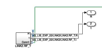
smbTofSimOut(simOut,Name)- returns T matrix and Time from a simulation |
 |
% smbTofSimOut(simOut,Name) - returns T matrix and Time from a simulation % (by Tim Lueth, SimMechanics, 2016-DEZ-18) % % For a signal name 'LINK.RF' there must be a signal 'LINK.RF_T.R' and % 'LINK.RF_T.t' % Use smbAddFrameSensor to create such signals for Reference Frames in % Sim Multi-Body (Status of: 2016-12-19) % % See also: smbSimulate, smbAddFrameSensor, smbTofSimOut, smbLogOutputPort % % [T,time]=smbTofSimOut(simOut,Name) % === INPUT PARAMETERS === % simOut: Simulation Result % Name: Name of Frame % === OUTPUT RESULTS ====== % T: Transformation matrix [4 x 4 x n] % time: time list [nx1] % % EXAMPLE: Try a simulation % VLFL_EXP20; % smbAddFrameSensor('LINK4.RF'); % simOut=smbSimulate(1); % [T,t]=smbTofSimOut(simOut,'LINK4.RF'); % whos T % |
smbLogOutputPort (block,Nr)- actives a Blocks's Output Port for Data logging |
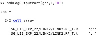 |
% smbLogOutputPort (block,Nr) - actives a Blocks's Output Port for Data % logging % (by Tim Lueth, SimMechanics, 2016-DEZ-17 as class: MODELING PROCEDURES) % % smbLogOutputPort(block,Nr) % === INPUT PARAMETERS === % block: Block % Nr: Output Port Number % |
smbAddFrameSensor (block)- adds s subsystem that records the frame movement |
 |
% smbAddFrameSensor (block) - adds s subsystem that records the frame % movement % (by Tim Lueth, SimMechanics, 2016-DEZ-17 as class: MODELING PROCEDURES) % % powerful procedure to track the movement of any frame (Status of: % 2016-12-27) % % See also: smbSimulate, smbTofSimOut % % smbAddFrameSensor([block]) % === INPUT PARAMETERS === % block: Name of coordinate frame in simMultibody % % EXAMPLE: Create frame movement list from simulation % VLFL_EXP20; % smbAddFrameSensor('LINK4.RF'); % simOut=smbSimulate(1); % [T,t]=smbTofSimOut(simOut,'LINK4.RF'); % whos T % |
smbSimulate(st)- starts the simulation of simscape multibody root |
 |
% smbSimulate(st) - starts the simulation of simscape multibody root % (by Tim Lueth, SimMechanics, 2016-DEZ-16 as class: ANALYZING PROCEDURES) % % See also: smbVideoSimulation, smwritevideo, sim % % [simOut,xout]=smbSimulate([st]) % === INPUT PARAMETERS === % st: stop time; default is 10 % === OUTPUT RESULTS ====== % simOut: simulation result % xout: xout parameter % % EXAMPLE: Try a simulation % VLFL_EXP20; % smbAddFrameSensor('LINK4.RF'); % simOut=smbSimulate(1); % [T,t]=smbTofSimOut(simOut,'LINK4.RF'); % whos T % |
smbVideoSimulation(st,vFName)- creates a video an shows the title in a figure |
 |
% smbVideoSimulation(st,vFName) - creates a video an shows the title in a figure % (by Tim Lueth, SimMechanics, 2016-DEZ-16 as class: VISUALIZATION) % % Creates a compressed 'motion jpeg avi' video of System 'bdroot' and % write into "bdroot.avi" in directory smbFileName % Takes about 10 seconds - as long as as the simulation (Status of: % 2017-01-01) % % See also: smbSimulate, smwritevideo, sim % % [i,vFName]=smbVideoSimulation([st,vFName]) % === INPUT PARAMETERS === % st: Stop time; default is 10 % vFName: Optional File name % === OUTPUT RESULTS ====== % i: Image of Frame 1 % vFName: Created FileName % |
smbCreateSGNode (p,SGName,SGcol,R)- creates a fixed node in SimMechanics |
 |
% smbCreateSGNode (p,SGName,SGcol,R) - creates a fixed node in % SimMechanics % (by Tim Lueth, SimMechanics, 2016-DEZ-16 as class: MODELING PROCEDURES) % % See also: smbCreateConnection, smbCreateSG, smbCreateSGJoint, % smbCreateStopJointC, smbCreateStopJointR, smbCopyConnections, % smbCreateDrive, smbCreateSineWave % % smbCreateSGNode([p,SGName,SGcol,R]) % === INPUT PARAMETERS === % p: position [x y z] % SGName: Name; default is Node % SGcol: Color; default is 'k' % R: Rotation Matrix; default is eye(3) % |
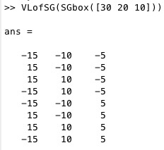
TofP(p)- returns a T matrix from a point in 2D or 3D |
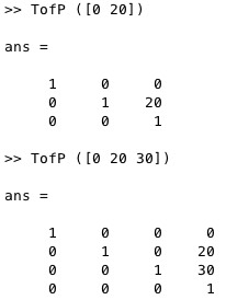 |
% TofP(p) - returns a T matrix from a point in 2D or 3D % (by Tim Lueth, VLFL-Lib, 2016-DEZ-16 as class: ANALYTICAL GEOMETRY) % % See also: TofR, TofVL, TPL, TofDPhiH, T3ofT2, T3P, T2P, TofPez, TofPEul % % T=TofP(p) % === INPUT PARAMETERS === % p: point [x y] or [x y z] % === OUTPUT RESULTS ====== % T: Transformation matrix 3x3 or 4x4 % % EXAMPLE: try: % TofP ([0 20]) % TofP ([0 20 30]) % |
SGofCPLT(CPL,T)- returns a extruded SG from a CPL and a final T matrix |
 |
% SGofCPLT(CPL,T) - returns a extruded SG from a CPL and a final T matrix % (by Tim Lueth, VLFL-Lib, 2016-DEZ-15 as class: MODELING PROCEDURES) % % SGofCPLT uses SGofCPLz. The x/y values of the translation Vector are % not used to guarantee that the cross sectional cut is unchanged. % (Status of: 2017-03-19) % % See also: SGofCPLz % % SG=SGofCPLT(CPL,[T]) % === INPUT PARAMETERS === % CPL: CPL of several contours % T: Transformation Matrix % === OUTPUT RESULTS ====== % SG: VL,FL,T,Tname % % EXAMPLE: Create a cylinder: % SG=SGofCPLT(PLcircle(10)); % SGplot(SG) % |
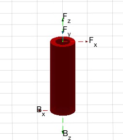
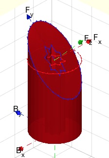
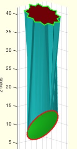
SGmodelNode(D,L,R,CPL,ez)- returns a solid geometry of a post as fixed node |
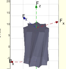 |
% SGmodelNode(D,L,R,CPL,ez) - returns a solid geometry of a post as fixed % node % (by Tim Lueth, VLFL-Lib, 2016-DEZ-15 as class: MODELING PROCEDURES) % % [SG,h,L]=SGmodelNode([D,L,R,CPL,ez]) % === INPUT PARAMETERS === % D: Diameter of the post; default is 10 % L: Height of the post; default is 15 % R: Rotation matrix; default is eye(3) % CPL: Contour of the post; default is PLstar(D,16); % ez: Orientation vector; [0 0 1]; [0 -1 0] etc. % === OUTPUT RESULTS ====== % SG: Solid Geoemtry % h: height of solid % L: % % EXAMPLE: Show the rotation of the posts: % SGmodelNode('','',rot(pi/6,0, 0)); % SGmodelNode('','',rot(0,pi/6, 0)); % SGmodelNode('','',rot(0, 0, pi/6)); % |
iscollofVLBB(VLA,VLB)- returs false if there is no collision/attaching |
 |
% iscollofVLBB(VLA,VLB) - returs false if there is no collision/attaching % (by Tim Lueth, VLFL-Lib, 2016-DEZ-15 as class: AUXILIARY PROCEDURES) % % See also: BBiscollofVL, BBofVL, CPLofBB, SGofBB, VLFLofBB, % outboundingbox, BBofSG % % c=iscollofVLBB(VLA,VLB) % === INPUT PARAMETERS === % VLA: Vertex list A % VLB: Vertex list B % === OUTPUT RESULTS ====== % c: true if bounding boxes collide or attach % % EXAMPLE: Show an example % [A,B]=SGanalyzeJoint (SGsample(17)); % iscollofVLBB(A.VL,B.VL) % |
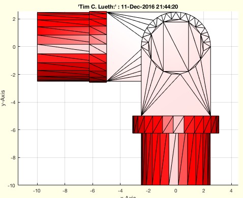
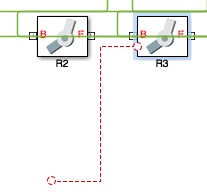
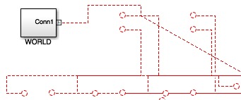
smbDrawNow(dsys,xy)- shows a snapshot of the simulink/simscape diagram |
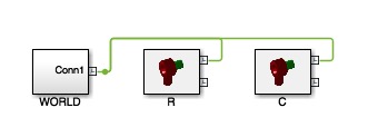 |
% smbDrawNow(dsys,xy) - shows a snapshot of the simulink/simscape diagram % (by Tim Lueth, SimMechanics, 2016-DEZ-14 as class: VISUALIZATION) % % This fnctn is based on a advice by Christoph Stockhammer, Mathworks, % Aachen. It always creates a file consisting of the current % simulink/simscape diagramm and opens it afterwards. Therefor it is % possible to get the files in the published documents. (Status of: % 2017-01-11) % % See also: smbDrawNow, drawnow, show, print % % LITERATURE: % Kevin Russell, Qiong Shen, Raj S. Sodhi (2013): Mechanism Design: % Visual and Programmable Approaches, CRC Press % % I=smbDrawNow([dsys,xy]) % === INPUT PARAMETERS === % dsys: optional system name; default is bdroot % xy: optional forced image size; [x y]; default is automatic % === OUTPUT RESULTS ====== % I: Image captured % |
exp_2016_12_14- EXPERIMENT TO CREATE Spherical Joints |
 |
% exp_2016_12_14 - EXPERIMENT TO CREATE Spherical Joints % (by Tim Lueth, VLFL-Lib, 2016-DEZ-14 as class: SIMMECHANICS INTERFACE) % % exp_2016_12_14 % |
SGanalyzeJointFaces(SG,)- returns joint type, Stator and Mover and Frame of Joint |
 |
% SGanalyzeJointFaces(SG,) - returns joint type, Stator and Mover and % Frame of Joint % (by Tim Lueth, VLFL-Lib, 2016-DEZ-13 as class: KINEMATICS AND FRAMES) % % WORK in PROGRESS % Fnctn to analyze two separated solids to detect the type of joint that % is implemented by those parts. % - Only two solids are allowed % - Corresponding Surfaces of Stator and Mover have to be closer than 1 % mm! (Status of: 2016-12-27) % % See also: SGanalyzeJointType, SGanalyzePenetration, SGanalyzeGroupParts % % [SGi,PL,CML]=SGanalyzeJointFaces(SG,[]) % === INPUT PARAMETERS === % SG: Solid Geometry % === OUTPUT RESULTS ====== % SGi: Cell list of Solid Geoemtries % PL: List containing set of penetrating parts % CML: Corresponding Faces % % EXAMPLE: Show an example % SGanalyzeJointFaces(SGsample(17)); % % |
SGanalyzePenetration(SG,m)- returns the structure of additive designed SG |
 |
% SGanalyzePenetration(SG,m) - returns the structure of additive designed SG % (by Tim Lueth, VLFL-Lib, 2016-DEZ-13 as class: SURFACES) % % Analyzes the solids with respect to penetration of solids using % different methods % - 'vertex': A penetration is detected based only on point of one solid % in another (slow) % - 'solid': : A penetration is detected based on boolean intersection % (very slow!) (Status of: 2017-03-17) % % See also: connectofmat, SGanalyzeJointType, SGanalyzeJointFaces, % SGanalyzeGroupParts % % [SGk,PL,CL]=SGanalyzePenetration(SG,[m]) % === INPUT PARAMETERS === % SG: Solid Geoemtry % m: method 'vertex','cross','solid'; default is cross % === OUTPUT RESULTS ====== % SGk: Cell list of Solid Geoemtries % PL: List containing set of penetrating parts % CL: Crossing List % % EXAMPLE: Analyze a joint consisting of two additive designed parts % SGanalyzePenetration(SGsample(17)) % |
SGbeating(SG,Rx,de,Ry)- beates a solid geoemtry on a cylinder or spherical ellipsoid |
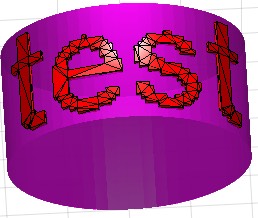 |
% SGbeating(SG,Rx,de,Ry) - beates a solid geoemtry on a cylinder or spherical ellipsoid % (by Tim Lueth, VLFL-Lib, 2016-DEZ-11 as class: SURFACES) % % ======================================================================= % OBSOLETE (2017-03-29) - USE FAMILY 'SGbending' INSTEAD % ======================================================================= % % This fnctn bends a solid geometry on a radial sphere (cylinder or % ball). The original solid is not modified, i.e. it is not intended to % add additional points on the surface before the bending: Long distances % will penetrate the sphere and are not bended. Bending is based on the % existing vertices of the solid % In case of text (Status of: 2017-03-27) % % See also: [ SGbending ] ; SGofCPLsphere, CPLofcontourc, contourc % % SG=SGbeating(SG,[Rx,de,Ry]) % === INPUT PARAMETERS === % SG: Solid Geometry % Rx: Radius of cylinder % de: distance/intrusion; default is -0.1 % Ry: Optional radius Rc; default is 10000 % === OUTPUT RESULTS ====== % SG: Solid Geometry % % EXAMPLE: % [A.VL,A.FL]=VLFLtextimage('test','',0); SGbeating(A,20) % |
VLFLofSG(SG)- returns one vertex list and one faces list for nested SG |
 |
% VLFLofSG(SG) - returns one vertex list and one faces list for nested SG % (by Tim Lueth, VLFL-Lib, 2016-DEZ-11 as class: AUXILIARY PROCEDURES) % % Since release 3.0, solid geometries can be cells of solid geometries. % This procedure returns recursively collected - similar to SGcat2 - the % complete list of vertices and faces. This for example required in % SGwriteSTL % SLOW AND RECURSIVE FUNCTION (Status of: 2016-12-11) % % See also: SGcat2, SGwriteSTL % % [VL,FL]=VLFLofSG(SG) % === INPUT PARAMETERS === % SG: Solid geometry potentially nested % === OUTPUT RESULTS ====== % VL: Vertex list % FL: Facet list % % EXAMPLE: % SG=SGmodelJoint('R',pi/2); % Create a joint consistinf of three solids % [A.VL,A.FL]=VLFLofSG(SG); % Convert into one Solid % SGfigure;SGplot(A); % Show the final solid % |
SGtransrelSG(SGA,SGB,rel,gap)- changes position of a solid relative to another solid |
 |
% SGtransrelSG(SGA,SGB,rel,gap) - changes position of a solid relative to another solid % (by Tim Lueth, VLFL-Lib, 2016-DEZ-07 as class: ANALYTICAL GEOMETRY) % % This fnctn replaces a set of other fnctns and does support the % transformation frames structure % Obsolete and should replaced by this fnctn: SGincenter, SGunder, % SGontop, SGinfront, SGbehind, SGleft, SGright, SGaligntop, % SGalignbottom, SGalignfront, SGalignback, SGalignleft, SGalignright % This fnctn supports also relative spatial arrangement relative to % frames (Status of: 2016-12-31) % % See also: TofSG, SGtransT, TofSG, SGaddrelSG % % [SG,T]=SGtransrelSG(SGA,SGB,[rel,gap]) % === INPUT PARAMETERS === % SGA: Transformed Solid Geometry % SGB: Final spatial transformation matix % rel: spatial relations % gap: gap, Optional parameter after an relation command % === OUTPUT RESULTS ====== % SG: Transformed Vertices and Frames % T: Transformation used to transform solid SGA % % EXAMPLE: Align relative to geometry and relative to frames % SGtransrelSG(SGA,SGB,'top','alignright',-5,alignback) % SGtransrelSG(B,A,'alignT',{'B','B'}) % |
exp_2016_12_07- Experiment for a Dreh-Schub-Gelenkk |
 |
% exp_2016_12_07 - Experiment for a Dreh-Schub-Gelenkk % (by Tim Lueth, SIM-Lib, 2016-DEZ-07 as class: EXPERIMENTS) % % exp_2016_12_07 % |
smbFilename(FName)- returns a temporary filename or directory |
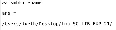 |
% smbFilename(FName) - returns a temporary filename or directory % (by Tim Lueth, SimMechanics, 2016-DEZ-06 as class: FILE HANDLING) % % The fnctn 'smbNewSystem' creates a temporary directory on the users % desktop to collect all temporary STL files that are generated during % the design. By calling 'smbFilename' without parameters, the directory % name is returned. By calling 'smbFilename' with a filename the full % directory path is returned. This fnctns defines the letters of the temp % directory and files. (Status of: 2016-12-27) % % See also: smbNewSystem, smbWhich, smbPSLibname, smbPSLibCompile % % fn=smbFilename([FName]) % === INPUT PARAMETERS === % FName: desired Filename % === OUTPUT RESULTS ====== % fn: full path of the desired filename % |
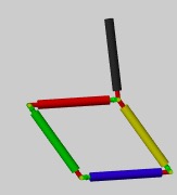
exp_2016_12_06- Experiment to Create 4-Bar Linkage from 4 physical % joints |
 |
% exp_2016_12_06 - Experiment to Create 4-Bar Linkage from 4 physical % % joints % (by Tim Lueth, SimMechanics, 2016-DEZ-06 as class: EXPERIMENTS) % % In this experiment Links and Joints are fully modelled as printable % solids. % The Geometrie is created using: SGmodelJoint and SGmodelLink % The SimScape Block are created using: smbCreateSGJoint, smbCreateSG. % Joint frames directed outwards. Link Frames are directed inwards. % For a final print process, it is necessary to melt the solids from the % joint with the solids of the connected link, to create the final solids % to print. (Status of: 2016-12-12) % % See also: smbNewSystem, SGmodelJoint, SGmodelLink, smbCreateSG, % smbCreateSGJoint, smbCreateConnection, smbCreateDrive, smbCreateSineWave % % exp_2016_12_06 % |
smbCreateSGJoint (JTyp,SGName,A,SFrame,EFrame)- Creating a Subsystem for a 3D Printable Jint |
 |
% smbCreateSGJoint (JTyp,SGName,A,SFrame,EFrame) - Creating a Subsystem % for a 3D Printable Jint % (by Tim Lueth, SimMechanics, 2016-DEZ-05) % % Basic procedure to create real joints consisting of several solids. % This fnctn is analog to smbCreateSG (Status of: 2016-12-06) % % See also: SGmodelJoint % % smbCreateSGJoint(JTyp,SGName,A,[SFrame,EFrame]) % === INPUT PARAMETERS === % JTyp: Rotational Type used for SGmodelJoint % SGName: Name within SimMechanics % A: Solid Geometry % SFrame: Block to be connected optionally to Stator % EFrame: Block to be connected optionally to Mover % |
exp_2016_12_05- Experiment to Create 4-Bar Linkage from 4 physical joints |
 |
% exp_2016_12_05 - Experiment to Create 4-Bar Linkage from 4 physical % joints % (by Tim Lueth, SimMechanics, 2016-DEZ-05 as class: EXPERIMENTS) % % In this experiment Links and Joints are fully modelled as printable % solids. % The Geometrie is created using: SGmodelJoint and SGmodelLink % The SimScape Block are created using: smbCreateSGJoint, smbCreateSG. % Joint frames directed outwards. Link Frames are directed inwards. % % For a final print process, it is necessary to melt the solids from the % joint with the solids of the connected link, to create the final solids % to print. % (Status of: 2016-12-06) % % See also: smbNewSystem, SGmodelJoint, SGmodelLink, smbCreateSG, % smbCreateSGJoint, smbCreateConnection, smbCreateDrive, smbCreateSineWave % % exp_2016_12_05 % |
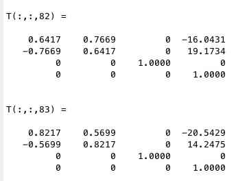
SGgetCenterPoint(A)- returns a point in the center of all vertices |
 |
% SGgetCenterPoint(A) - returns a point in the center of all vertices % (by Tim Lueth, VLFL-Lib, 2016-DEZ-04 as class: ANALYTICAL GEOMETRY) % % used as simple mass center approximation. At later stage it makes sense % to calculate it using SGarea and facet based (Status of: 2016-12-05) % % See also: SGarea % % p=SGgetCenterPoint(A) % === INPUT PARAMETERS === % A: Solid Geoemtry % === OUTPUT RESULTS ====== % p: point % |
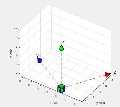
RLplot(RL,VL)- plots along the z axis the systems of a Euler Rotation List |
 |
% RLplot(RL,VL) - plots along the z axis the systems of a Euler Rotation % List % (by Tim Lueth, VLFL-Lib, 2016-DEZ-04 as class: ANALYTICAL GEOMETRY) % % RLplot(RL,[VL]) % === INPUT PARAMETERS === % RL: Euler Angle Rotation List % VL: Vertex list or distance between points % % EXAMPLE: Simple Rotation % RL=RLofEulerInterpolation(5,[0 0 0],[pi 0 0] ) % RLplot(RL) % |
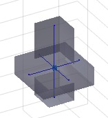
exp_2016_12_04- EXperiement to show how to implement joins as separated Solids |
 |
% exp_2016_12_04 - EXperiement to show how to implement joins as % separated Solids % (by Tim Lueth, SimMechanics, 2016-DEZ-04 as class: EXPERIMENTS) % % Took a long time in Qingdao to implement (Status of: 2016-12-05) % % exp_2016_12_04 % |
smbGetSubSystempath(block)- smb returns the filepath of the current block |
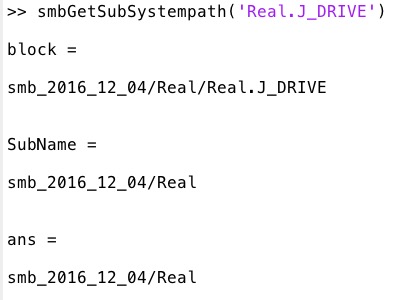 |
% smbGetSubSystempath(block) - smb returns the filepath of the current block % (by Tim Lueth, SimMechanics, 2016-DEZ-04 as class: AUXILIARY PROCEDURES) % % try also fileparts(gcb) (Status of: 2016-12-05) % % See also: smbWhich, fileparts % % [SubName,block]=smbGetSubSystempath(block) % === INPUT PARAMETERS === % block: % === OUTPUT RESULTS ====== % SubName: % block: % |
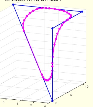
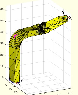
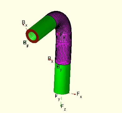
SGofCPLCVLR(CPL,CVL,R,R1,R2)- Returns a solid of a contour along a path |
 |
% SGofCPLCVLR(CPL,CVL,R,R1,R2) - Returns a solid of a contour along a path % (by Tim Lueth, VLFL-Lib, 2016-DEZ-03 as class: EXPERIMENTS) % % Fnctn to study or for lazy people. It helps to show some fats progress, % Nevertheless, the solution is simular to euler angle not intuitive. % (Status of: 2016-12-31) % % See also: SGcontourtube, RLofEulerInterpolation, VLinsertEulerSteps, % VLradialEdges, TofPez % % [C,CVL]=SGofCPLCVLR(CPL,CVL,[R,R1,R2]) % === INPUT PARAMETERS === % CPL: Closed Polygone Line % CVL: Vertex path along a contour in 3D % R: Optionl radius for VLradialEdges % R1: Optional euler anlge, Rotation Matrix or T matrix of start % R2: Optional euler anlge, Rotation Matrix or T matrix of end % === OUTPUT RESULTS ====== % C: Solid Geometry % CVL: Finally Used 3D path % % EXAMPLE: Create a Tube % VL=[0 0 0; 0 0 10; 0 0 20; 10 0 20; 15 0 20; 20 0 20]; % CPL=[PLcircle(5);NaN NaN;PLcircle(3,4)]; % SGofCPLCVLR(CPL,VL,2); % SGofCPLCVLR(4,10); % Short Version if radius and z % SGofCPLCVLR(4,[10 10 10]); % Short Version if radius and ez vector % |
TofPez(p,ez)- creates a T matrix from point and ez-Vector |
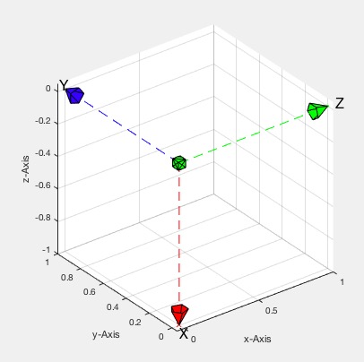 |
% TofPez(p,ez) - creates a T matrix from point and ez-Vector % (by Tim Lueth, VLFL-Lib, 2016-DEZ-03 as class: ANALYTICAL GEOMETRY) % % Special case is if ez=[1 0 0] or [-1 0 0] (Status of: 2016-12-27) % % See also: SGcontourtube, RLofEulerInterpolation, VLinsertEulerSteps, % VLradialEdges % % T=TofPez(p,ez) % === INPUT PARAMETERS === % p: point % ez: ez-vector length is not relevant % === OUTPUT RESULTS ====== % T: Transformation matrix; ex is set by default % |
RL2exl(RL)- returns X vectors for a list of euler angles |
 |
% RL2exl(RL) - returns X vectors for a list of euler angles % (by Tim Lueth, VLFL-Lib, 2016-DEZ-03 as class: ANALYTICAL GEOMETRY) % % EXL=RL2exl(RL) % === INPUT PARAMETERS === % RL: Rotation List of Euler Angles % === OUTPUT RESULTS ====== % EXL: List of ex vectors % |
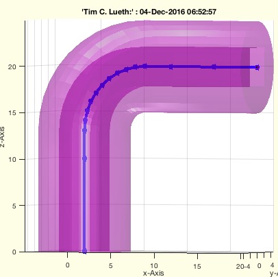
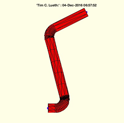
VLradialEdges(VL,R)- returns a vertex list (VL) with rounded edges |
 |
% VLradialEdges(VL,R) - returns a vertex list (VL) with rounded edges % (by Tim Lueth, VLFL-Lib, 2016-DEZ-03 as class: ANALYZING PROCEDURES) % % Replaces edges by a radial curve. The desired radius can be reduced % automatically if necessary. It is possible to maximize the radius % automatically. % In case that R is negative; VLbreakEdges is used instead (Status of: % 2017-02-13) % % See also: PLradialEdges, SGcontourtube, RLofEulerInterpolation, % VLinsertEulerSteps, TofPez, PLtangentcirc, VLtangentcirc, % SGbreakCorners, SGradialCorners % % NVL=VLradialEdges(VL,[R]) % === INPUT PARAMETERS === % VL: Vertex list nx3 % R: Radius; default is 10 % === OUTPUT RESULTS ====== % NVL: New vertex list % % EXAMPLE: % VL=roundn(rand(6,3)*100,5) % VLradialEdges(VL,2) % VLradialEdges([0 0 0;0 0 100; 100 0 100;100 100 100]); view(0,0) % VLradialEdges([0 0 0;0 0 100; 100 0 0],10); view(0,0) % |
exp_2016_12_03- Experiment to create 3D pathes with constraints (Radius) |
 |
% exp_2016_12_03 - Experiment to create 3D pathes with constraints % (Radius) % (by Tim Lueth, VLFL-Lib, 2016-DEZ-03 as class: EXPERIMENTS) % % A 3D path with start and end frames can have additional constraints % regarding edge radius and turning angles. The edge radius is required % for mass movement or for bend cables in vessel structures. The turning % angle condition is required since otherwise the outside contour may % strangulate the outside geometry of a contour (Status of: 2016-12-03) % % exp_2016_12_03 % |
TofPEul(p,eul)- return from euler angle and position an HT matrix |
 |
% TofPEul(p,eul) - return from euler angle and position an HT matrix % (by Tim Lueth, VLFL-Lib, 2016-DEZ-02 as class: ANALYTICAL GEOMETRY) % % See also: TofR, TofVL, TPL, TofDPhiH, T3ofT2, T3P, T2P, TofP, TofPez % % T=TofPEul(p,eul) % === INPUT PARAMETERS === % p: Point in 3D % eul: Euler angle [phiz phiy phix] % === OUTPUT RESULTS ====== % T: Homogenous Transformation Matrix % |
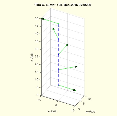
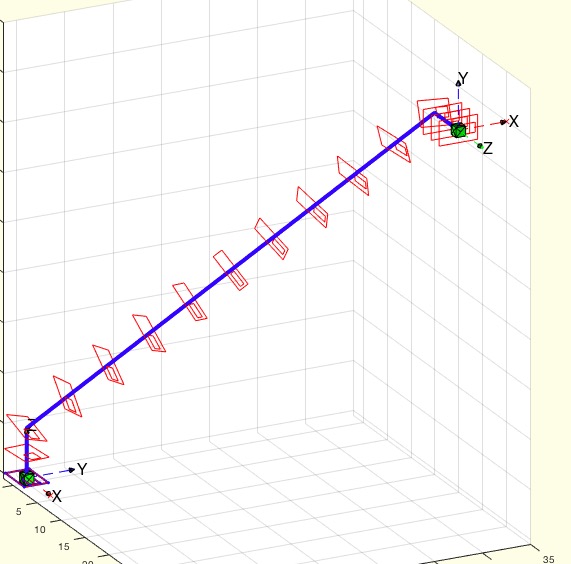
RLofEulerInterpolation(VL,e1,e2)- Returns euler rotations as linear interpolation |
 |
% RLofEulerInterpolation(VL,e1,e2) - Returns euler rotations as linear % interpolation % (by Tim Lueth, VLFL-Lib, 2016-DEZ-02 as class: ANALYTICAL GEOMETRY) % % Creates Euler rotation list (ZYX) for a linear turning interpolation % along a path in 3D. The ez vector is always in the direction of the % path. There will be a warning of the path does not fulfill the % condition that the euler angle fits to the direction. % VLinsertEulerSteps hast to be called afterwards if there is twist on % long distances % (Status of: 2016-12-27) % % See also: VLinsertEulerSteps, RL2exl, SGcontourtube, % VLinsertEulerSteps, VLradialEdges, TofPez % % [RL,L,DL,NL,EXL]=RLofEulerInterpolation(VL,e1,e2) % === INPUT PARAMETERS === % VL: Vertex list (nx3) or scalar n % e1: ZYX-Euler angle for first Vertex VL(1,:) or matrix T1,R1 % e2: ZYX-Euler angle for last Vertex VL(end,:) or matrix T2,R2 % === OUTPUT RESULTS ====== % RL: Rotation list of euler angles (n x 3) % L: Length of path, scalar % DL: Distance vector; last one closes (n x 3) % NL: Norm of distance vectors (n x 1) % EXL: Optional List of % % EXAMPLE: Just try % VL=[0 0 0; 0 0 10; 40 40 40; 50 40 40]; % RLofEulerInterpolation(VL,[0 0 0],[0 pi/2 0]) % % |
exp_2016_12_02- Experiment to create 3D pathes with constraints |
 |
% exp_2016_12_02 - Experiment to create 3D pathes with constraints % (by Tim Lueth, VLFL-Lib, 2016-DEZ-02 as class: EXPERIMENTS) % % A 3D path with start and end frames can have additional constraints % regarding edge radius and turning angles. The edge radius is required % for mass movement or for bend cables in vessel structures. The turning % angle condition is required since otherwise the outside contour may % strangulate the outside geometry of a contour (Status of: 2016-12-03) % % exp_2016_12_02 % |
VLinsertEulerSteps(VL,e1,e2,gw)- inserts vertex points on straight lines if the twist angle is to large |
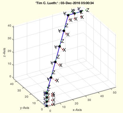 |
% VLinsertEulerSteps(VL,e1,e2,gw) - inserts vertex points on straight % lines if the twist angle is to large % (by Tim Lueth, VLFL-Lib, 2016-DEZ-02 as class: ANALYTICAL GEOMETRY) % % See also: RLofEulerInterpolation, SGcontourtube, % RLofEulerInterpolation, VLradialEdges, TofPez % % NVL=VLinsertEulerSteps(VL,e1,e2,[gw]) % === INPUT PARAMETERS === % VL: Vertex list (nx3) % e1: ZYX-Euler angle for first Vertex VL(1,:) % e2: ZYX-Euler angle for last Vertex VL(end,:) % gw: limiting angle; default is pi/16 % === OUTPUT RESULTS ====== % NVL: New Vertex list % % EXAMPLE: Just try % VL=[0 0 0; 0 0 10; 0 0 20; 10 0 20; 15 0 20; 20 0 20]; % VLinsertEulerSteps(VL,[0 0 0],[0 pi/2 0]) % % |
exp_2016_12_01(T1,T2)- Experiment to improve VLRadiusC |
 |
% exp_2016_12_01(T1,T2) - Experiment to improve VLRadiusC % (by Tim Lueth, VLFL-Lib, 2016-DEZ-01 as class: ANALYTICAL GEOMETRY) % % VLRadiusC should be as perfect as PLradialEdges, The new name is % VLradialEdges (Status of: 2016-12-01) % % HTL=exp_2016_12_01(T1,T2) % === INPUT PARAMETERS === % T1: % T2: % === OUTPUT RESULTS ====== % HTL: % |
exp_2016_11_30- EXPERIMENT how to simply create contours |
 |
% exp_2016_11_30 - EXPERIMENT how to simply create contours % (by Tim Lueth, VLFL-Lib, 2016-NOV-30 as class: EXPERIMENTS) % % In contrast to 2016_11_29 only the x-direction is given in addition to % VL (Status of: 2016-12-03) % % exp_2016_11_30 % |
exp_2016_11_31- Experiment to show Florian Schleich how to use the Lib |
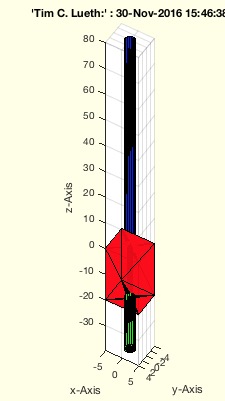 |
% exp_2016_11_31 - Experiment to show Florian Schleich how to use the Lib % (by Tim Lueth, VLFL-Lib, 2016-NOV-30 as class: EXPERIMENTS) % % A simple example for a surgical suction (Status of: 2016-11-30) % % exp_2016_11_31 % |
SGradialCorners_old(A,vi,R)- should breaks corners and edges of solids |
 |
% SGradialCorners_old(A,vi,R) - should breaks corners and edges of solids % (by Tim Lueth, VLFL-Lib, 2016-NOV-30 as class: SURFACES) % % Completely new version on 2017-20-12 based on exp_2017_02_12. (Status % of: 2017-02-12) % % See also: SGbreakvertices, SGradialCorners, VLradialEdges % % A=SGradialCorners_old([A,vi,R]) % === INPUT PARAMETERS === % A: Solid Geometry % vi: list of corned index (n) or corner vertex list (nx3); default is 4 % R: radius; default is 1mm % === OUTPUT RESULTS ====== % A: Solid Geometry with rounded corners % |
exp_2016_11_29a- EXPERIMENT for creating SGof2SGT, SGof2T |
 |
% exp_2016_11_29a - EXPERIMENT for creatinh SGof2SGT, SGof2T % (by Tim Lueth, VLFL-Lib, 2016-NOV-29 as class: EXPERIMENTS) % % See also: SGof2SGT, SGof2T % % HTL=exp_2016_11_29a % === OUTPUT RESULTS ====== % HTL: % |
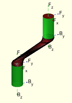
SGof2CVL(CVL1,CVL2)- returns a solid that closes two |
 |
% SGof2CVL(CVL1,CVL2) - returns a solid that closes two % (by Tim Lueth, VLFL-Lib, 2016-NOV-29 as class: SURFACES) % % This fnctn is comparable to SGof2CPLz but works for 3D Closed Vertex % Contours. The walls are always straight. Therefore the contour returns % an empty solution, if both contours are (Status of: 2017-03-19) % % See also: SGof2SGT, SGof2T, SGof2CPLz % % [SG,FLW,FLA,FLB]=SGof2CVL(CVL1,CVL2) % === INPUT PARAMETERS === % CVL1: Plane closed contour 1 % CVL2: Plane closed contour 2 % === OUTPUT RESULTS ====== % SG: Solid Geometry of the Solid SG.VL=[CVL1;CVL2] % FLW: Facet lit of the wall % FLA: Facet lit of contour plate 1 % FLB: Facet lit of contour plate 2 % % EXAMPLE: % CVL1=VLaddz(PLcircle(10,4)) % CVL2=VLtransT(CVL1,[rot(0,pi/6,0), [0 0 40]';0 0 0 1]) % SGof2CVL(CVL1,CVL2) % |
exp_2016_11_29- EXPERIMENT to connect two solids by a contour tube |
 |
% exp_2016_11_29 - EXPERIMENT to connect two solids by a contour tube % (by Tim Lueth, VLFL-Lib, 2016-NOV-29 as class: EXPERIMENTS) % % See also: SGconnect, SGconnect2T, SGcontourtube % % exp_2016_11_29 % |
TofSG(SG,rel)- sets a HT matrix relativ to nested solid |
 |
% TofSG(SG,rel) - sets a HT matrix relativ to nested solid % (by Tim Lueth, VLFL-Lib, 2016-NOV-27 as class: ANALYTICAL GEOMETRY) % % Nested solid geometries are allowed % rel such as 'ontop','up', 'under','down', 'left', 'right', 'infront', % 'behind' (Status of: 2016-11-27) % % See also: TofDPhi, TofDPhiH, TofPCVL, TofR, TofSGML, TofSGMLez, TofVL, % TofVLFLULfi, TofVLUL, TofVLULez % % T=TofSG(SG,[rel]) % === INPUT PARAMETERS === % SG: Solid Geoemtry % rel: relations or ez-vector % === OUTPUT RESULTS ====== % T: Frame % |
VLofSG(SG)- returns for nested cell solids the vertex list |
 |
% VLofSG(SG) - returns for nested cell solids the vertex list % (by Tim Lueth, VLFL-Lib, 2016-NOV-27 as class: AUXILIARY PROCEDURES) % % In constrast to write simply VL=SG.VL; this procedure supports nested % Solids {SG1,SG2,…} (Status of: 2016-11-27) % % See also: VLofgca, VLofimage, VLofSG, VLofVM,TatSG % % VL=VLofSG(SG) % === INPUT PARAMETERS === % SG: NEsted Solid Geoemtry; cells of cells of solids % === OUTPUT RESULTS ====== % VL: Vertex list % |
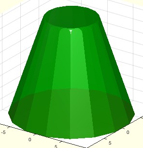
exp_2016_11_25- Creates hollow links for mechanisms |
 |
% exp_2016_11_25 - Creates hollow links for mechanisms % (by Tim Lueth, VLFL-Lib, 2016-NOV-25 as class: MODELING PROCEDURES) % % exp_2016_11_25 % % EXAMPLE: Just try: % exp_2016_11_25 % |
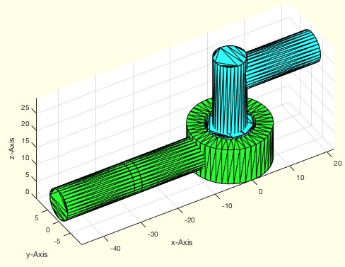
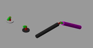
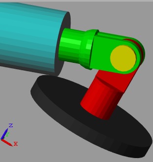
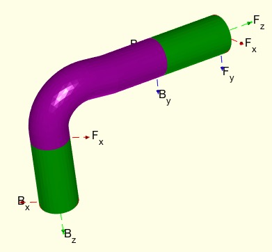
SGmodelJoint(Ty,pos,SL,EL)- returns 3 separated Solids for automated design of joints |
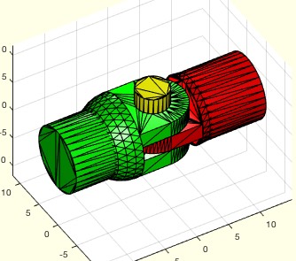 |
% SGmodelJoint(Ty,pos,SL,EL) - returns 3 separated Solids for automated % design of joints % (by Tim Lueth, VLFL-Lib, 2016-NOV-24 as class: MODELING PROCEDURES) % % Joint Solids consist of at least two Solids SG1, SG2 in a cell % structure {SG1,SG2}. Alle SOlids have to have a base frame "B" and a % follower frame 'F'. The turning point is the base frame of all links. % The follower frame is the contact point for all connecting elememts. In % outher words % SG{i}.T{1}=Base Frame % SG{i}.T{2}=Follower Frame % SG{1}.T{2}=Frame 1 of joint % SG{2}.T{2}=Frame 2 of joint % (Status of: 2016-12-10) % % [SMJ,TB,TF]=SGmodelJoint([Ty,pos,SL,EL]) % === INPUT PARAMETERS === % Ty: Type % pos: position parameter % SL: Design of stator flange (0,1,) default 0 % EL: Design of mover flange (0,1,) default 0 % === OUTPUT RESULTS ====== % SMJ: Surface model of the joint % TB: % TF: % |
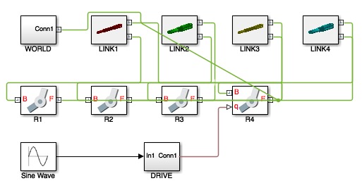
VLFL_EXP21- Creates a 4-bar-Linkage and Drives it actively |
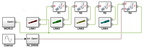 |
% VLFL_EXP21 - Creates a 4-bar-Linkage and Drives it actively % (by Tim Lueth, VLFL-Lib, 2016-NOV-24 as class: EXPERIMENTS) % % Tutorial (Status of: 2016-11-24) % % VLFL_EXP21 % |
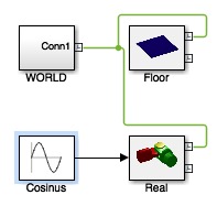
smbCreateSineWave (SName,EPort,amp)- Creates a Cosinus Wave as Simulink Signal |
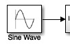 |
% smbCreateSineWave (SName,EPort,amp) - Creates a Cosinus Wave as Simulink Signal % (by Tim Lueth, SimMechanics, 2016-NOV-24 as class: AUXILIARY PROCEDURES) % % See also: smbCreateConnection, smbCreateSG, smbCreateSGJoint, % smbCreateSGNode, smbCreateStopJointC, smbCreateStopJointR, % smbCopyConnections, smbCreateDrive % % smbCreateSineWave([SName,EPort,amp]) % === INPUT PARAMETERS === % SName: Generator name; default is 'Sine Wave' % EPort: Optional Port to connect % amp: optional amplitude; default is +pi % |
smbDeleteDrive (Joint)- SimMechanics removes the drive block of a joint |
 |
% smbDeleteDrive (Joint) - SimMechanics removes the drive block of a joint % (by Tim Lueth, SimMechanics, 2016-NOV-24 as class: MODELING PROCEDURES) % % See also: smbDeleteUnconnectedLines % % smbDeleteDrive(Joint) % === INPUT PARAMETERS === % Joint: Name of joint; default is gcb % |
smbDeleteUnconnectedLines(asys)- removes unconnecte lines in Simulink/SimMechanics |
 |
% smbDeleteUnconnectedLines(asys) - removes unconnecte lines in Simulink/SimMechanics % (by Tim Lueth, SimMechanics, 2016-NOV-24 as class: MODELING PROCEDURES) % % See also: smbAddLine, smbNewLineRouting % % smbDeleteUnconnectedLines([asys]) % === INPUT PARAMETERS === % asys: system to handel; default is gcs % |
exp_2016_11_24- Creates a 4-bar-Linkage and Drives it actively |
 |
% exp_2016_11_24 - Creates a 4-bar-Linkage and Drives it actively % (by Tim Lueth, VLFL-Lib, 2016-NOV-24 as class: EXPERIMENTS) % % Same Tutorial as VLFL_EXP21 (Status of: 2016-12-03) % % exp_2016_11_24 % |
exp_2016_11_23- creates a SimMEchanics Fourbarjoin |
 |
% exp_2016_11_23 - creates a SimMEchanics Fourbarjoin % (by Tim Lueth, SimMechanics, 2016-NOV-23 as class: EXPERIMENTS) % % exp_2016_11_23 % |
smbCreateDrive (Joint)- SimMechanics adds a position control block to an existing joint |
 |
% smbCreateDrive (Joint) - SimMechanics adds a position control block to % an existing joint % (by Tim Lueth, SimMechanics, 2016-NOV-23) % % The input signal of a drive is a Simulink signal (Status of: 2016-12-27) % % See also: smbCreateConnection, smbCreateSG, smbCreateSGJoint, % smbCreateSGNode, smbCreateStopJointC, smbCreateStopJointR, % smbCopyConnections, smbCreateSineWave % % smbCreateDrive(Joint) % === INPUT PARAMETERS === % Joint: Joint name; default is gcb % |
smbAddBlock (SysName,BlockName,LibPath,BlockExt)- Auxiliary function to create Block for Simulink/SimScape |
 |
% smbAddBlock (SysName,BlockName,LibPath,BlockExt) - Auxiliary fnctn to create Block for Simulink/SimScape % (by Tim Lueth, SimMechanics, 2016-NOV-23 as class: MODELING PROCEDURES) % % See also: smbAddLine, smbAddFrame, smbAddFrameSensor % % smbAddBlock([SysName,BlockName,LibPath,BlockExt]) % === INPUT PARAMETERS === % SysName: System Name; default is gcs % BlockName: Block name % LibPath: Library path % BlockExt: optional Block extension] % |
smbGetBlockInfo(Block)- Auxiliary function to get information on simulink/simscape structures |
 |
% smbGetBlockInfo(Block) - Auxiliary fnctn to get information on simulink/simscape structures % (by Tim Lueth, SimMechanics, 2016-NOV-22 as class: MODELING PROCEDURES) % % [Name,Blockpath,LibPath]=smbGetBlockInfo(Block) % === INPUT PARAMETERS === % Block: Block Name; default is gcb % === OUTPUT RESULTS ====== % Name: Name of Block % Blockpath: Part of Block % LibPath: Library Path % |