New in SG-Lib 3.0
SGiso4762(M,L)- SG of Hexagon socket set screw with cylindric head |
 |
% SGiso4762(M,L) - SG of Hexagon socket set screw with cylindric head % (by Tim Lueth, VLFL-Lib, 2016-NOV-21 as class: MECHANICAL PROCEDURES) % % returns a solid geometry of a "Hexagon socket set screw with flat % point" related to DIN912 or ISO4762 (Status of: 2017-01-29) % % See also: DINhelp, DIN913, SGiso4026, DIN912, DIN336 % % SG=SGiso4762(M,L) % === INPUT PARAMETERS === % M: Diameter (millimeter) % L: Length (millimeter) % === OUTPUT RESULTS ====== % SG: Solid geoemetry of Hexagon socket set screw with flat point % |
DIN912(M)- returns the DIN912/ISO4762 table for a metric threads |
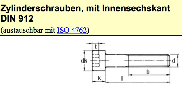 |
% DIN912(M) - returns the DIN912/ISO4762 table for a metric threads % (by Tim Lueth, VLFL-Lib, 2016-NOV-21 as class: MECHANICAL PROCEDURES) % % The table DIN912/ISO4762 has the following columns. All values are % given in millimeter % 1) d Metric outer diameter in mm % 2) s width of imbus % 3) t min dpeht of imbus % 4) b min length of thread % 5) k max height of head % 6) dk max outer diameter of head (Status of: 2017-01-29) % % See also: DINhelp, DIN913, SGiso4026, DIN336, SGiso4762 % % [M,TL]=DIN912(M) % === INPUT PARAMETERS === % M: metric treat diameter % === OUTPUT RESULTS ====== % M: M that was used for the table entry % TL: Table entry for M % |
exp_2016_11_21- Creates a set of Iso4026 / DIN913 Screws |
 |
% exp_2016_11_21 - Creates a set of Iso4026 / DIN913 Screws % (by Tim Lueth, VLFL-Lib, 2016-NOV-21 as class: MODELING PROCEDURES) % % exp_2016_11_21 % |
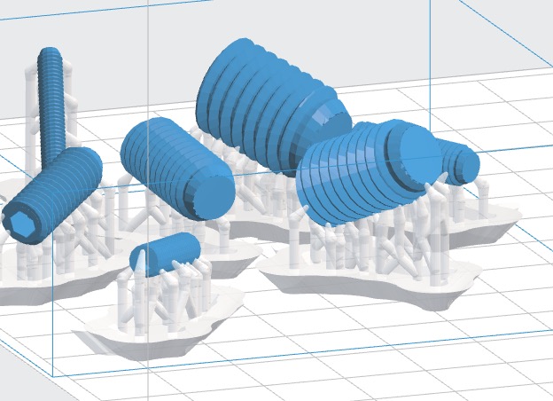
exp_2016_11_22- Creates a set of imbus screws with cylindric head |
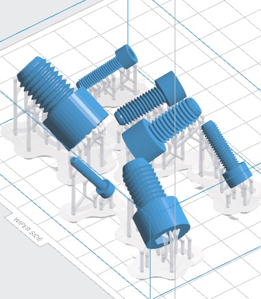 |
% exp_2016_11_22 - Creates a set of imbus screws with cylindric head % (by Tim Lueth, VLFL-Lib, 2016-NOV-21 as class: MODELING PROCEDURES) % % Iso4762 / DIN912 % (Status of: 2016-11-24) % % exp_2016_11_22 % |
VLFL_EXP20- |
 |
% VLFL_EXP20 - % (by Tim Lueth, VLFL-Lib, 2016-NOV-19 as class: EXPERIMENTS) % % VLFL_EXP20 % |
smbWhich(BName)- return the full path name for a given block name |
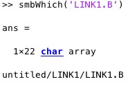 |
% smbWhich(BName) - return the full path name for a given block name % (by Tim Lueth, SimMechanics, 2016-NOV-19 as class: MODELING PROCEDURES) % % This fnctn looks for all systems and (Status of: 2016-12-27) % % See also: smbNewSystem, smbFilename, smbPSLibname, smbPSLibCompile % % fullpath=smbWhich(BName) % === INPUT PARAMETERS === % BName: Block name % === OUTPUT RESULTS ====== % fullpath: full name of the block including system % % EXAMPLE: % tut_2016_11_16 % smbWhich('LINK1.B') % |
smbNewGridPos(Nr,Grid,Colum)- return grid positions for new blocks |
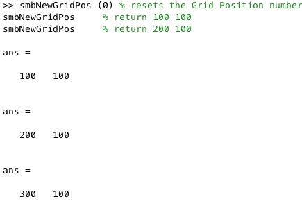 |
% smbNewGridPos(Nr,Grid,Colum) - return grid positions for new blocks % (by Tim Lueth, SimMechanics, 2016-NOV-18 as class: MODELING PROCEDURES) % % This auxiliary fnctn helps to create new SimMechanics block at grid % positions. % Since Dec. 2016, the fnctn analyzes the current systems and uses the % next free grid position (Status of: 2017-01-08) % % See also: smbPosgcb, smbSetPosition % % [p,Np]=smbNewGridPos([Nr,Grid,Colum]) % === INPUT PARAMETERS === % Nr: Current number of Grid position; default is 0 % Grid: Grid size; default is [100 100] % Colum: Number of columns; default is 5 % === OUTPUT RESULTS ====== % p: [x y] of a grid % Np: % % EXAMPLE: % smbNewGridPos (0) % resets the Grid Position number return 100 100 % smbNewGridPos % return 200 100 % smbNewGridPos % return 300 100 % |
smbSGtransP(SGName,delta)- Moves a SG without changing the |
 |
% smbSGtransP(SGName,delta) - Moves a SG without changing the % (by Tim Lueth, SimMechanics, 2016-NOV-16) % % smbSGtransP(SGName,delta) % === INPUT PARAMETERS === % SGName: Solid Name that has Baseframe and Follower Frame % delta: Delta vector % |
smbCreateConnection(F1,F2,T)- adds a connection line between 2 blocks. |
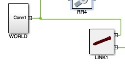 |
% smbCreateConnection(F1,F2,T) - adds a connection line between 2 blocks. % (by Tim Lueth, SimMechanics, 2016-NOV-16) % % This fnctn connects Block within SimScape not in Simulink! So make sure % that the used Block have just one Input Port. % Blocks are typically such as .S (Stator), .M(Mover), .B(Base), % .F(Follower) % Without any T parameter, the blocks are connected directly. % With parameter 'align', there will be a rotation around y to connect % two links or two joint. Solids have their frames looking inside. Joints % have their frames towards outside. (Status of: 2016-12-27) % % See also: smbCreateSG, smbCreateSGJoint, smbCreateSGNode, % smbCreateStopJointC, smbCreateStopJointR, smbCopyConnections, % smbCreateDrive, smbCreateSineWave % % h=smbCreateConnection(F1,F2,[T]) % === INPUT PARAMETERS === % F1: Frame 1 % F2: Frame 2 % T: Additional Frame for rotation; 'match','align' % === OUTPUT RESULTS ====== % h: handle to line % % EXAMPLE: smbCreateConnection('WORLD.ORIGIN','LINK1.B'); % |
smbGetPortofFrame(FName)- returns the subsystem Port for a given subsystem Frame |
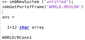 |
% smbGetPortofFrame(FName) - returns the subsystem Port for a given % subsystem Frame % (by Tim Lueth, SimMechanics, 2016-NOV-16) % % See also: smbNewSystem, SGmodelLink, SGmodelLink, smbCreateJoint % % % PName=smbGetPortofFrame(FName) % === INPUT PARAMETERS === % FName: Frame Name in a Subsystem % === OUTPUT RESULTS ====== % PName: Name of Port in the Current System % % EXAMPLE: Show the Port Name of the Origin Frame % smbNewSystem ('test_smb_lib'); % smbGetPortofFrame('WORLD.ORIGIN') % % |
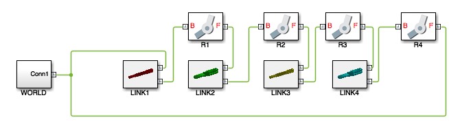
exp_2016_11_16- Creates a SimMechanics Multi-Body Simulation for a 4Bar linkage |
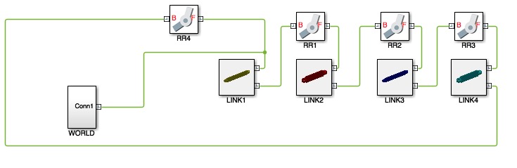 |
% exp_2016_11_16 - Creates a SimMechanics Multi-Body Simulation for a % 4Bar linkage % (by Tim Lueth, SimMechanics, 2016-NOV-16 as class: EXPERIMENTS) % % Creates a SimMechanics Multi-Body Simulation for a 4Bar linkage. % All smb* fnctns require Matlab Version 2016b. (Status of: 2016-11-21) % % LITERATURE: % - Tim C. Lueth (2016) : MiMed Internal Report Nr. 5626 ''Creating a % Fourbar-Linkage using Matlab-Toolbox "SG-Lib" as Solid-Modeler, % "SimMechanics" as Simulator and 3D-Printer "Formlab2" for Additive % Manufacturing'', Technische Universität München, Institute of Micro % Technology and Medical Device Engineering, File: % 16-11-20_MIMED_LUETH-005626.PDF % % exp_2016_11_16 % |
smbGetAllLines(Block)- returns a connecting list of Blocks an Port |
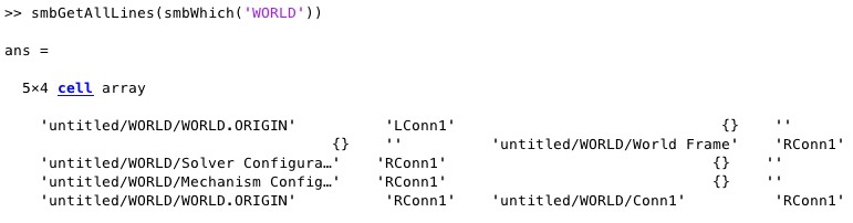 |
% smbGetAllLines(Block) - returns a connecting list of Blocks an Port % (by Tim Lueth, SimMechanics, 2016-NOV-15) % % LL=smbGetAllLines(Block) % === INPUT PARAMETERS === % Block: Block, Block list, System % === OUTPUT RESULTS ====== % LL: List of connections (n x 4) % |
smbGetConnectedBlocks(Block)- returns a list with connected blocks of a block or system |
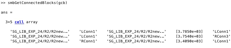 |
% smbGetConnectedBlocks(Block) - returns a list with connected blocks of % a block or system % (by Tim Lueth, SimMechanics, 2016-NOV-15) % % This procedure helps to see the connected blocks and the ports to % connect (Status of: 2016-12-26) % % See also: smbWhich, smbNameofPort % % CBL=smbGetConnectedBlocks(Block) % === INPUT PARAMETERS === % Block: Block or System or list of Blockss % === OUTPUT RESULTS ====== % CBL: Connect Block List (cell) % % EXAMPLE: All connections of the current system % smbGetConnectedBlocks (gcs) % smbGetConnectedBlocks(smbWhich('G489')) % |
smbCreateJoint(JType,JName,SFrame,EFrame)- creates a joint block in the actual system |
 |
% smbCreateJoint(JType,JName,SFrame,EFrame) - creates a joint block in % the actual system % (by Tim Lueth, SimMechanics, 2016-NOV-15) % % See also: smbNewSystem, smbCreateSG, smbCreateConnection, smbCreateJoint % % BName=smbCreateJoint([JType,JName,SFrame,EFrame]) % === INPUT PARAMETERS === % JType: Joint Type ['R','H','P','C','E','S','G,'W'];; default='W' % JName: 'Joint Name'; default=random number % SFrame: Start Frame to connect (must exist already); default='' % EFrame: End Frame to connect (must exist already); default='' % === OUTPUT RESULTS ====== % BName: Block handle name % % EXAMPLE: Create an revolute joint % smbNewSystem ('untitled'); % smbCreateJoint('R'); % |
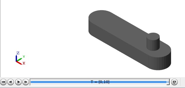
SGmodelLink1(L,D,SL,EL,DH,DL)- SG of a cylindric rod |
 |
% SGmodelLink1(L,D,SL,EL,DH,DL) - SG of a cylindric rod % (by Tim Lueth, VLFL-Lib, 2016-NOV-14 as class: SIMMECHANICS INTERFACE) % % Creates a cylindric solid bar for the creation of Mechanisms that can % be 3D-printed using SLS or SLA. % % w=135; DL=D/2/tan(pi/360*(180-w)) % (Status of: 2017-01-17) % % See also: SGmodelLink, SGmodelLink2, SGmodelLink3 % % [SG,w]=SGmodelLink1([L,D,SL,EL,DH,DL]) % === INPUT PARAMETERS === % L: Length % D: Diameter % SL: Base Level % EL: Frame Level % DH: Hole Diameter; default is D/4 % DL: Length of the flange; default is 2*D~150 degree % === OUTPUT RESULTS ====== % SG: Solid Geometry % w: maximum turning angle % % EXAMPLE: SGmodelLink1(80,8,3,3); % |
SGmodelLink(L,D,SL,EL,DH,DL)- SG of a cylindric rod |
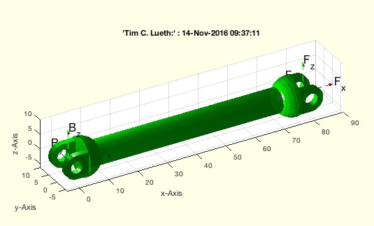 |
% SGmodelLink(L,D,SL,EL,DH,DL) - SG of a cylindric rod % (by Tim Lueth, VLFL-Lib, 2016-NOV-14 as class: SIMMECHANICS INTERFACE) % % Creates a cylindric solid bar for the creation of Mechanisms that can % be 3D-printed using SLS or SLA. % % w=135; DL=D/2/tan(pi/360*(180-w)) % (Status of: 2016-11-21) % % [SG,w]=SGmodelLink([L,D,SL,EL,DH,DL]) % === INPUT PARAMETERS === % L: Length % D: Diameter % SL: Base Level % EL: Frame Level % DH: Hole Diameter; default is D/4 % DL: Length of the flange; default is 2*D~150 degree % === OUTPUT RESULTS ====== % SG: Solid Geometry % w: maximum turning angle % % EXAMPLE: SGmodelLink(80,8,3,3); % |
smbSetPosition (BName,P,O,s)- Sets Position Size Orientation of Blocks |
 |
% smbSetPosition (BName,P,O,s) - Sets Position Size Orientation of Blocks % (by Tim Lueth, SimMechanics, 2016-NOV-13 as class: AUXILIARY PROCEDURES) % % See also: smbPosgcb, smbNewGridPos % % smbSetPosition(BName,[P,O,s]) % === INPUT PARAMETERS === % BName: Block name or gcs % P: Position % O: orientation('right','up','left','down'; default is is unchanged % s: size; default is unchanged % % EXAMPLE: smbSetPosition(gcs,smbNewGridPos,'up') % |
smbSetTransformationMatrix (BName,T,rel)- Sets a Block Transformation |
 |
% smbSetTransformationMatrix (BName,T,rel) - Sets a Block Transformation % (by Tim Lueth, SimMechanics, 2016-NOV-13) % % Only the R and t part of the HT matrix are used. If the third parameter % is used, the Rotation part is turned % rel='match' - T is unchanged % rel='align' - T is turned around y-axis (Status of: 2016-12-14) % % See also: smbSetTransformationMatrix, smbSetRotationMatrix, % smbSetTranslationVector, smbCreateSG % % smbSetTransformationMatrix(BName,T,[rel]) % === INPUT PARAMETERS === % BName: Block Name or gcb % T: 4x4 Transformation Matrix % rel: default is 'match' % |
smbSetTranslationVector (BName,t)- Sets a Block Translation in mm |
 |
% smbSetTranslationVector (BName,t) - Sets a Block Translation in mm % (by Tim Lueth, SimMechanics, 2016-NOV-13) % % smbSetTranslationVector(BName,t) % === INPUT PARAMETERS === % BName: Block Name or gcb % t: Translation Vector (x y z) % |
smbSetRotationMatrix (BName,R)- Sets a Block Rotation Matrix |
 |
% smbSetRotationMatrix (BName,R) - Sets a Block Rotation Matrix % (by Tim Lueth, SimMechanics, 2016-NOV-13) % % smbSetRotationMatrix(BName,R) % === INPUT PARAMETERS === % BName: Block Name or gcb % R: 3x3 Rotation Matrix % |
SGwriteIcon (SG,FName)- Writes an Icon/JPG File with a 3D view of a SG |
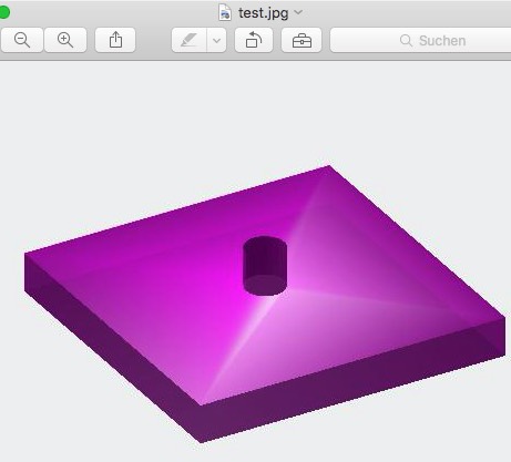 |
% SGwriteIcon (SG,FName) - Writes an Icon/JPG File with a 3D view of a SG % (by Tim Lueth, VLFL-Lib, 2016-NOV-12 as class: FILE HANDLING) % % SGwriteIcon(SG,FName) % === INPUT PARAMETERS === % SG: Solid Geometry % FName: Full File Name. The Extension defines the Format (.JPG, .PNG) % |
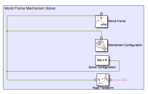
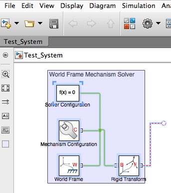
smbCreateSG(SG,SGName,SGcol,SFrame,EFrame)- SimMechanics creates a subsystem for a Solid Geometry |
 |
% smbCreateSG(SG,SGName,SGcol,SFrame,EFrame) - SimMechanics creates a % subsystem for a Solid Geometry % (by Tim Lueth, SimMechanics, 2016-NOV-12 as class: SIMMECHANICS % INTERFACE) % % This fnctn writes the Solid Geometry as STL File on Disk in the Desktop % and loads it into a newly ceated SimMechanics Solid block. % All Frames of the Solid are turned inside the solid by rotating around % y pi/2! (Status of: 2016-12-14) % % See also: smbNewSystem, smbCreateJoint, smbSetTransformationMatrix, % smbSetPosition, smbAddLine, smbConvertSubsystem, SGwriteIcon, SGwriteSTL % % u=smbCreateSG(SG,[SGName,SGcol,SFrame,EFrame]) % === INPUT PARAMETERS === % SG: Solid Geometry % SGName: SG Name within SimMechanics; default is 'SOLID' % SGcol: Solid Color ('w',.....'); default is SG.col % SFrame: Optional Block to connect the Base % EFrame: Optional Block to connect the Follower % === OUTPUT RESULTS ====== % u: % % EXAMPLE: % load AIM_SGrobot.mat % smbNewSystem ('Test_System') % smbCreateSG (SG2,'Link2') % smbAddLine('World Frame Mechanism Solver/RConn1','Link2.Solid/RConn1') % |
smbExpandSubsystem (SSName)- SimMechanics expanding a subsystem |
 |
% smbExpandSubsystem (SSName) - SimMechanics expanding a subsystem % (by Tim Lueth, SimMechanics, 2016-NOV-11) % % This procedure is just a call of a Simulink class procedure. The % Subsystem name must include the system % path:< % % See also: smbCreateSubsystem, smbExpandSubsystem, smbConvertSubsystem % % smbExpandSubsystem(SSName) % === INPUT PARAMETERS === % SSName: Name of Subsystem. If empty gcb is used % % EXAMPLE: smbExpandSubsystem('test_fourbar/Subsystem') % |
smbConvertSubsystem(SSName,blocks)- SimMechanics converts blocks to a subsystem |
 |
% smbConvertSubsystem(SSName,blocks) - SimMechanics converts blocks to a % subsystem % (by Tim Lueth, SimMechanics, 2016-NOV-11) % % This procedure is the core of smbCreateSubsystem. % (Status of: 2016-11-13) % % See also: smbCreateSubsystem, smbExpandSubsystem, smbConvertSubsystem % % % smbConvertSubsystem(SSName,blocks) % === INPUT PARAMETERS === % SSName: SubSystem Name % blocks: List of Blocks % |
smbCreateSubsystem(SSName)- SimMechanics creates and opens a subsystem |
 |
% smbCreateSubsystem(SSName) - SimMechanics creates and opens a subsystem % (by Tim Lueth, SimMechanics, 2016-NOV-11) % % The susbsytem file is created in the current working directory (pwd) % (Status of: 2016-11-19) % % See also: smbCreateSubsystem, smbExpandSubsystem, smbConvertSubsystem % % smbCreateSubsystem(SSName) % === INPUT PARAMETERS === % SSName: Namestring of a Subsystem % |
smbSysPortLineTable(SName)- SimMechanics returns the block and ports and line tables |
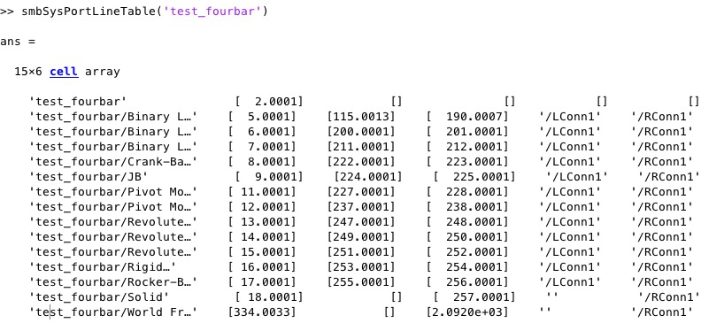 |
% smbSysPortLineTable(SName) - SimMechanics returns the block and ports % and line tables % (by Tim Lueth, SimMechanics, 2016-NOV-11) % % bht=smbSysPortLineTable(SName) % === INPUT PARAMETERS === % SName: % === OUTPUT RESULTS ====== % bht: % |
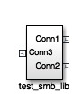
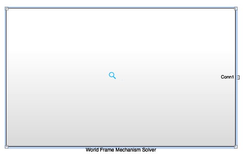
smbNewSystem (SName,grav)- SimMechanics creates an empty new system |
 |
% smbNewSystem (SName,grav) - SimMechanics creates an empty new system % (by Tim Lueth, SimMechanics, 2016-NOV-10 as class: MODELING PROCEDURES) % % Attention: An existing open system would be cleared by this approach. % The system name must fulfill the conditions of a Matlab fnctn name (no % spaces, no starting number, etc.) (Status of: 2016-12-27) % % See also: smbCreateSubsystem, smbCreateSG, smbCreateJoint, % smbConvertSubsystem % % smbNewSystem(SName,[grav]) % === INPUT PARAMETERS === % SName: Desired name for new system (No spaces allowed) % grav: gravity vector; default is 5.66 m/s2 * [-1 -1 -1] (9.81) % % EXAMPLE: Open an new SimMechanics Multi Body Sheet % smbNewSystem ('test_smb_lib') % |
smbGetAllPorts(SName)- SimMechanics returns the port of block |
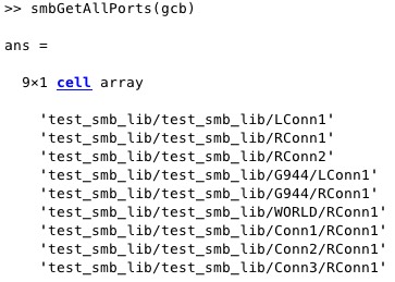 |
% smbGetAllPorts(SName) - SimMechanics returns the port of block % (by Tim Lueth, SimMechanics, 2016-NOV-10) % % See also: smbGetPorts, smbGetConnectedBlocks % % % [PL,CL]=smbGetAllPorts(SName) % === INPUT PARAMETERS === % SName: Name of System or Block; if empty gcs is used % === OUTPUT RESULTS ====== % PL: List of all Port Strings % CL: List of all Connectable Ports % |
smbGetPorts(Block)- SimMechanics returns the port of block |
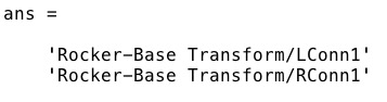 |
% smbGetPorts(Block) - SimMechanics returns the port of block % (by Tim Lueth, SimMechanics, 2016-NOV-10) % % It is necessary to name the system (Status of: 2016-11-10) % % See also: smbAddFrame, smbAddLine, gcb % % PN=smbGetPorts(Block) % === INPUT PARAMETERS === % Block: Name of Block including system; if empty gcb is used % === OUTPUT RESULTS ====== % PN: Cell of Port Strings % % EXAMPLE: smbGetPorts ('test_fourbar/Frame 3') % |
smbAddLine(P1,P2)- SimMechanics creates line between block ports |
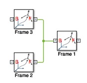 |
% smbAddLine(P1,P2) - SimMechanics creates line between block ports % (by Tim Lueth, SimMechanics, 2016-NOV-10 as class: MODELING PROCEDURES) % % See also: smbDeleteUnconnectedLines, smbAddBlock, smbAddFrame, % smbAddFrameSensor % % h=smbAddLine(P1,P2) % === INPUT PARAMETERS === % P1: Name of Port 1 % P2: Name of Port 2 % === OUTPUT RESULTS ====== % h: handle to Line % % EXAMPLE: Create two Rigid Tranformation and draw a line: % smbAddFrame('Frame 1');smbAddFrame('Frame 2');smbAddFrame('Frame 3'); % smbAddLine('Frame 1/LConn1','Frame 2/Rconn1') % smbAddLine('Frame 1/LConn1','Frame 3/Rconn1') % |
smbAddFrame(FName)- SimMechanics creates a Rigid Transformation Block |
 |
% smbAddFrame(FName) - SimMechanics creates a Rigid Transformation Block % (by Tim Lueth, SimMechanics, 2016-NOV-10 as class: MODELING PROCEDURES) % % See also: smbAddLine, smbAddBlock, Sensor % % h=smbAddFrame(FName) % === INPUT PARAMETERS === % FName: String with the Tranformation Name % === OUTPUT RESULTS ====== % h: handle to Block % % EXAMPLE: smbAddFrame ('Frame 1') % |
exp_2016_10_27- Creates STL files for a cover for the HEBI IO Module |
 |
% exp_2016_10_27 - Creates STL files for a cover for the HEBI IO Module % (by Tim Lueth, VLFL-Lib, 2016-OKT-27 as class: MODELING PROCEDURES) % % exp_2016_10_27 % |
exp_2016_09_28- Creates STL files for a cover for the HEBI IO Module |
 |
% exp_2016_09_28 - Creates STL files for a cover for the HEBI IO Module % (by Tim Lueth, VLFL-Lib, 2016-SEP-28 as class: MODELING PROCEDURES) % % exp_2016_09_28 % |
SGui(mag,c)- Opens a dialog, reads and plots an STL-File |
 |
% SGui(mag,c) - Opens a dialog, reads and plots an STL-File % (by Tim Lueth, VLFL-Lib, 2016-SEP-19 as class: USER INTERFACE) % % Same as VLFLui (Status of: 2016-09-19) % % [SG,filename,pathname]=SGui([mag,c]) % === INPUT PARAMETERS === % mag: magnification; default is 1 % c: Color of Object, Plots only if color is defined % === OUTPUT RESULTS ====== % SG: Solid Geoemtry of STL File % filename: filename of selected file % pathname: pathname of selected file % % EXAMPLE: Read in a STL File % [SG]=SGui % |
SGcapsulate(SG,d,align,delta)- capsules a solid including alignment |
 |
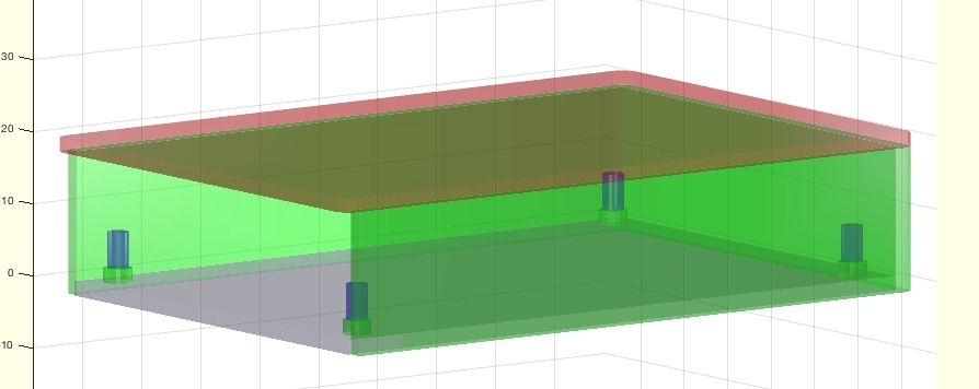
% SGcapsulate(SG,d,align,delta) - capsules a solid including alignment % (by Tim Lueth, VLFL-Lib, 2016-JUL-06 as class: SURFACES) % % WORK in progress (Status of: 2016-07-06) % % SGX=SGcapsulate(SG,d,[align,delta]) % === INPUT PARAMETERS === % SG: Solid geometry % d: wall thickness % align: 'top','bottom','left','right','front','back' % delta: shift relative to alignment % === OUTPUT RESULTS ====== % SGX: Resulting solid % % EXAMPLE: % SG=SGof2CPLz(PLcircle(10,18),PLcircle(4),40); % SGcapsulate(SG,5,'top'); show % |
SGfurniture(typ,a,pos,xyz,par)- Solid geoemtries of sample furniture |
 |
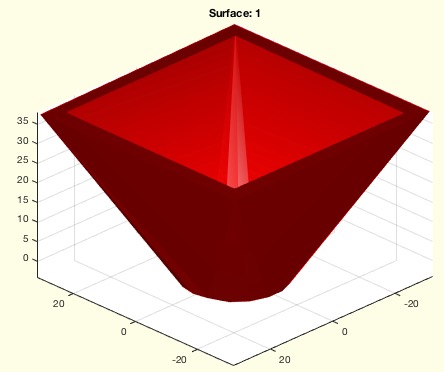
% SGfurniture(typ,a,pos,xyz,par) - Solid geoemtries of sample furniture % (by Tim Lueth, VLFL-Lib, 2016-JUL-03 as class: MODELING PROCEDURES) % % Try: box, couch, locker, table, chair, haslev, carpet, balkon (Status % of: 2016-07-05) % % SG=SGfurniture([typ,a,pos,xyz,par]) % === INPUT PARAMETERS === % typ: box, couch, locker, table, chair, haslev, carpet, balkon % a: turning angle in deg % pos: shift vector in [x y z] % xyz: dimensions as x y % par: parameter beside dimensions % === OUTPUT RESULTS ====== % SG: Solid geoemtry % % EXAMPLE: SGfurniture('box','','',[30 20 10]); % SGfurniture('couch','','',[200 100 40]); % SGfurniture('couch','','',[200 100 40],[80 0]); % SGfurniture('couch','','',[200 100 40],[80 60]); % |
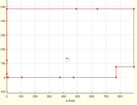
SGofFloorplan(FP,a,w,H,Z,td)- creates from solid geometry of floor plan |
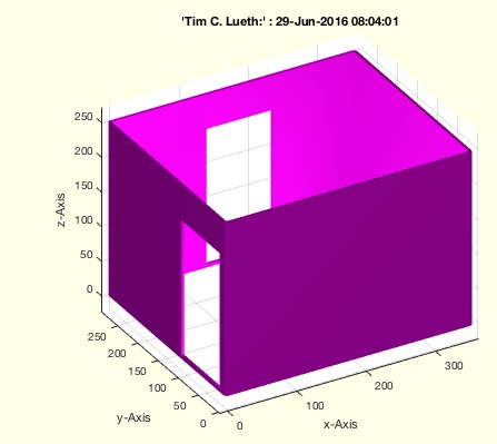 |
% SGofFloorplan(FP,a,w,H,Z,td) - creates from solid geometry of floor plan % (by Tim Lueth, VLFL-Lib, 2016-JUN-22 as class: SURFACES) % % Uses procedure PLofFloorplan to create the point list (Status of: % 2016-06-29) % % [SG,ST]=SGofFloorplan(FP,[a,w,H,Z,td]) % === INPUT PARAMETERS === % FP: Floor plan list [wall length, angle [opening]] % a: optional final turning angle % w: optional wall thickness; default is 4 % H: optional building height; default is 250 % Z: Thickness of windows % td: dimension text; default is false % === OUTPUT RESULTS ====== % SG: Solid Geometry % ST: Windows Geometry % % EXAMPLE: Simple room floor plan % SR=[10 0; 95 0; 182 90; 137 0; 95 0; 118 90; 287 90; 350 90;]; % R=SGofFloorplan(SR); SGfigure(R); view (-30,30) % |
PLgrow(PL,w,edge)- grows a contour line in a distance to an open or closed PL |
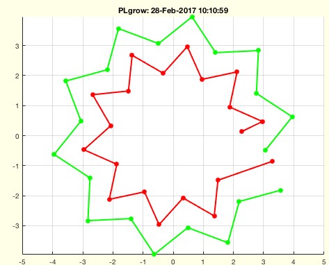 |
% PLgrow(PL,w,edge) - grows a contour line in a distance to an open or closed PL % (by Tim Lueth, VLFL-Lib, 2016-JUN-21 as class: CLOSED POLYGON LISTS) % % This fnctn handles point lists which is more complex than the handling % of CPL since the starting point and end point have to be considered in % 4 different cases. (Status of: 2017-02-28) % % See also: PLoutercontour, CPLoutercontour, CPLgrow % % [RPL,ENL,PNL,PDL]=PLgrow(PL,w,[edge]) % === INPUT PARAMETERS === % PL: Polygon line % w: distance for growing % edge: true call CPLgrowEdge; default is false; % === OUTPUT RESULTS ====== % RPL: Recalculated CPL % ENL: Edge normal vector list % PNL: Point normal vector lit % PDL: Point direction vector list % % EXAMPLE: % PLgrow(PLcircle(4),-1); % PLgrow(PLstar(4,20),-1); % PLgrow(PLstar(10,12),-3,true); % |
isPL(PL)- PL has no NaN separator, 1st and last point are different |
 |
% isPL(PL) - PL has no NaN separator, 1st and last point are different % (by Tim Lueth, VLFL-Lib, 2016-JUN-21 as class: AUXILIARY PROCEDURES) % % returns true if PL argument is a point list, i.e. the list does not % contain NaN separator row, and 1st and last point in the list are % different. (Status of: 2016-06-21) % % b=isPL(PL) % === INPUT PARAMETERS === % PL: Point List, (nx2) or (nxm) % === OUTPUT RESULTS ====== % b: true if PL has no NaN separator, 1st and last point are different % % EXAMPLE: Compare the result of: % isPL(rand(10,2)) % isPL(CPLofPL(rand(10,2))) % |
PLofFloorPlan(FP)- Returns a point list from a distance angle list |
 |
% PLofFloorPlan(FP) - Returns a point list from a distance angle list % (by Tim Lueth, VLFL-Lib, 2016-JUN-20 as class: CLOSED POLYGON LISTS) % % PL=PLofFloorPlan(FP) % === INPUT PARAMETERS === % FP: Distance Angle List % === OUTPUT RESULTS ====== % PL: Point List % |
testdateTL- returns a string for publishable function |
 |
% testdateTL - returns a string for publishable fnctn % (by Tim Lueth, VLFL-Lib, 2016-JUN-14 as class: AUXILIARY PROCEDURES) % % Tested 14-Jun-2016 11:39:46 by 'timlueth' using Matlab 9.0.0.341360 % (R2016a) on a MACI64 (Status of: 2016-06-14) % % testdateTL % % EXAMPLE: testdateTL % |